Jeep Cherokee (XJ): Compressor clutch
The refrigerant system can remain fully-charged during compressor clutch, pulley, or coil replacement.
The compressor clutch can be serviced in the vehicle.
REMOVAL
(1) Disconnect and isolate the battery negative cable.
(2) Remove the serpentine drive belt. Refer to Group 7 - Cooling System for the procedures.
(3) Unplug the compressor clutch coil wire harness connector.
(4) Remove the four bolts that secure the compressor to the mounting bracket.
(5) Remove the compressor from the mounting bracket. Support the compressor in the engine compartment while servicing the clutch.
(6) Insert the two pins of the spanner wrench (Special Tool C-4489) into the holes of the clutch plate. Hold the clutch plate stationary and remove the hex nut (Fig. 20).
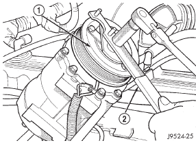
Fig. 20 Clutch Nut Remove
1 - CLUTCH PLATE
2 - SPANNER
(7) Remove the clutch plate with a puller (Special Tool C-6461) (Fig. 21).
(8) Remove the compressor shaft key and the clutch shims.
(9) Remove the external front housing snap ring with snap ring pliers (Fig. 22).
(10) Install the lip of the rotor puller (Special Tool C-6141-1) into the snap ring groove exposed in the previous step, and install the shaft protector (Special Tool C-6141-2) (Fig. 23).
(11) Install the puller through-bolts (Special Tool C-6461) through the puller flange and into the jaws of the rotor puller and tighten (Fig. 24). Turn the puller center bolt clockwise until the rotor pulley is free.
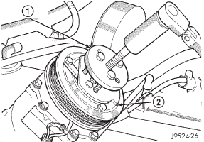
Fig. 21 Clutch Plate Remove
1 - CLUTCH PLATE PULLER
2 - CLUTCH PLATE

Fig. 22 External Snap Ring Remove
1 - PULLEY
2 - SNAP RING PLIERS
(12) Remove the screw and retainer from the clutch coil lead wire harness on the compressor front housing (Fig. 25).
(13) Remove the snap ring from the compressor hub and remove the clutch field coil (Fig. 26). Slide the clutch field coil off of the compressor hub.
INSPECTION
Examine the friction surfaces of the clutch pulley and the front plate for wear. The pulley and front plate should be replaced if there is excessive wear or scoring.
If the friction surfaces are oily, inspect the shaft and nose area of the compressor for oil. Remove the felt from the front cover. If the felt is saturated with oil, the shaft seal is leaking and the compressor must be replaced.
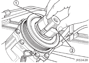
Fig. 23 Shaft Protector and Puller
1 - PULLER JAW
2 - SHAFT PROTECTOR
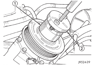
Fig. 24 Install Puller Plate
1 - PULLER JAW
2 - PULLER
Check the clutch pulley bearing for roughness or excessive leakage of grease. Replace the bearing, if required.
INSTALLATION
(1) Install the clutch field coil and snap ring.
(2) Install the clutch coil lead wire harness retaining clip on the compressor front housing and tighten the retaining screw.
(3) Align the rotor assembly squarely on the front compressor housing hub.
(4) Install the pulley bearing assembly with the installer (Special Tool C-6871) (Fig. 27). Thread the installer on the shaft, then turn the nut until the pulley assembly is seated.
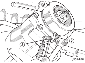
Fig. 25 Clutch Coil Lead Wire Harness
1 - COIL
2 - COIL WIRE
3 - RETAINER SCREW
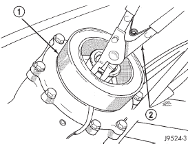
Fig. 26 Clutch Field Coil Snap Ring Remove
1 - COIL
2 - SNAP RING PLIERS
(5) Install the external front snap ring with snap ring pliers. The bevel side of the snap ring must be facing outward. Press the snap ring to make sure it is properly seated in the groove.
CAUTION: If the snap ring is not fully seated in the groove it will vibrate out, resulting in a clutch failure and severe damage to the front housing of the compressor.
(6) Install the compressor shaft key and the original clutch shims on the compressor shaft.
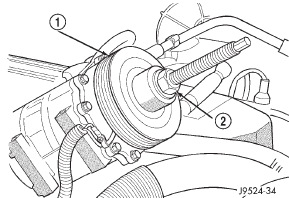
Fig. 27 Clutch Pulley Install
1 - PULLEY BEARING ASSEMBLY
2 - INSTALLER
(7) Install the clutch plate with the driver (Special Tool C-6463) (Fig. 28). Install the shaft hex nut and tighten to 14.4 N·m (10.5 ft. lbs.).
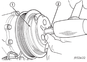
Fig. 28 Clutch Plate Driver
1 - CLUTCH PLATE
2 - DRIVER
(8) Check the clutch air gap with a feeler gauge (Fig. 29). If the air gap does not meet the specification, add or subtract shims as required. The air gap specification is 0.41 to 0.79 millimeter (0.016 to 0.031 inch). If the air gap is not consistent around the circumference of the clutch, lightly pry up at the minimum variations. Lightly tap down at the points of maximum variation.
NOTE: The air gap is determined by the spacer shims. When installing an original, or a new clutch assembly, try the original shims first. When installing a new clutch onto a compressor that previously did not have a clutch, use 1.0, 0.50, and 0.13 millimeter (0.040, 0.020, and 0.005 inch) shims from the clutch hardware package that is provided with the new clutch.
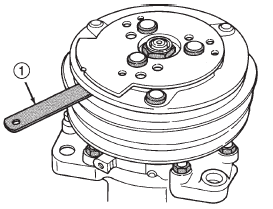
Fig. 29 Check Clutch Air Gap
1 - FEELER GAUGE
(9) Reverse the remaining removal procedures to complete the installation.
CLUTCH BREAK-IN
After a new compressor clutch has been installed, cycle the compressor clutch approximately twenty times (five seconds on, then five seconds off). During this procedure, set the heater-A/C control to the Recirculation Mode, the blower motor switch in the highest speed position, and the engine speed at 1500 to 2000 rpm. This procedure (burnishing) will seat the opposing friction surfaces and provide a higher compressor clutch torque capability.
 Blower motor relay. Blower motor resistor. Compressor
 Compressor clutch relay. Condenser. Dual function high pressure
switch/high pressure cut-off
switch
Other materials:
Cleaning and inspection
AX5 MANUAL TRANSMISSION COMPONENTS
GENERAL INFORMATION
Clean the transmission components in solvent. Dry
the cases, gears, shift mechanism and shafts with
compressed air. Dry the bearings with clean, dry
shop towels only. Never use compressed air on the
bearings. This could cause severe damage ...
