 Jeep Cherokee Service ManualHorn systems » Diagnosis and testing
Horn relay
Horn relay
The horn relay (Fig. 2) is located in the junction block on the right cowl side inner panel below the instrument panel in the passenger compartment. If a problem is encountered with a continuously sounding horn, it can usually be quickly resolved by removing the horn relay from the junction block until further diagnosis is completed. Refer to Junction Block in the Contents of Group 8W - Wiring Diagrams for horn relay identification and location. For complete circuit diagrams, refer to Horn/Cigar Lighter in the Contents of Group 8W - Wiring Diagrams.
WARNING: ON VEHICLES EQUIPPED WITH AIRBAGS, REFER TO GROUP 8M - PASSIVE RESTRAINT SYSTEMS BEFORE ATTEMPTING ANY STEERING WHEEL, STEERING COLUMN, OR INSTRUMENT PANEL COMPONENT DIAGNOSIS OR SERVICE. FAILURE TO TAKE THE PROPER PRECAUTIONS COULD RESULT IN ACCIDENTAL AIRBAG DEPLOYMENT AND POSSIBLE PERSONAL INJURY.
(1) Remove the horn relay from the junction block.
Refer to Horn Relay in the Removal and Installation section of this group for the procedures.
(2) A relay in the de-energized position should have continuity between terminals 87A and 30, and no continuity between terminals 87 and 30. If OK, go to Step 3. If not OK, replace the faulty relay.
(3) Resistance between terminals 85 and 86 (electromagnet) should be 75 6 5 ohms. If OK, go to Step 4. If not OK, replace the faulty relay.
(4) Connect a battery to terminals 85 and 86.
There should now be continuity between terminals 30 and 87, and no continuity between terminals 87A and 30. If OK, perform the Relay Circuit Test that follows. If not OK, replace the faulty relay.
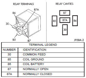
Fig. 2 Horn Relay
RELAY CIRCUIT TEST
(1) The relay common feed terminal cavity (30) is connected to battery voltage and should be hot at all times. If OK, go to Step 2. If not OK, repair the open circuit to the fuse in the junction block as required.
(2) The relay normally closed terminal (87A) is connected to terminal 30 in the de-energized position, but is not used for this application. Go to Step 3.
(3) The relay normally open terminal (87) is connected to the common feed terminal (30) in the energized position. This terminal supplies battery voltage to the horn(s). There should be continuity between the cavity for relay terminal 87 and the horn relay output circuit cavity of each horn wire harness connector at all times. If OK, go to Step 4. If not OK, repair the open circuit to the horn(s) as required.
(4) The coil battery terminal (86) is connected to the electromagnet in the relay. It is connected to battery voltage and should be hot at all times. Check for battery voltage at the cavity for relay terminal 86. If OK, go to Step 5. If not OK, repair the open circuit to the fuse in the junction block as required.
(5) The coil ground terminal (85) is connected to the electromagnet in the relay. It is grounded through the horn switch when the horn switch is depressed. On vehicles equipped with the Remote Keyless Entry (RKE) system, the horn relay coil ground terminal can also be grounded by the RKE receiver in response to certain inputs related to the RKE system. Check for continuity to ground at the cavity for relay terminal 85. There should be continuity with the horn switch depressed, and no continuity with the horn switch released. If not OK, refer to Horn Switch in the Diagnosis and Testing section of this group.
Horn relay
Horn switch
Horn
Jeep Cherokee Service Manual
- Lubrication and maintenance
- Suspension
- Differential and driveline
- Brakes
- Clutch
- Cooling system
- Battery
- Starting systems
- Charging system
- Ignition system
- Instrument panel systems
- Audio systems
- Horn systems
- Speed control system
- Turn signal and hazard warning systems
- Wiper and washer systems
- Lamps
- Passive restraint systems
- Electrically heated systems
- Power distribution systems
- Power lock systems
- Vehicle theft/security systems
- Power seat systems
- Power window systems
- Power mirror systems
- Chime/buzzer warning systems
- Overhead console systems
- Engine
- Exhaust system
- Frame and bumpers
- Frame
- Fuel system
- Steering
- Transmission and transfer case
- Tires and wheels
- Body
Categories
