 Jeep Cherokee Service ManualDifferential and driveline » 194 RBI axle » Adjustments
Pinion gear depth
Pinion gear depth
GENERAL INFORMATION
Ring and pinion gears are supplied as matched sets only. The identifying numbers for the ring and pinion gear are etched into the face of each gear (Fig.
64). A plus (+) number, minus (-) number or zero (0) is etched into the face of the pinion gear. This number is the amount (in thousandths of an inch) the depth varies from the standard depth setting of a pinion etched with a (0). The standard setting from the center line of the ring gear to the back face of the pinion is 96.850 mm (3.813 in.). The standard depth provides the best teeth contact pattern. Refer to Backlash and Contact Pattern Analysis Paragraph in this section for additional information.
Fig. 64 Pinion Gear ID Numbers
1 - PRODUCTION NUMBERS
2 - DRIVE PINION GEAR DEPTH VARIANCE
3 - GEAR MATCHING NUMBER (SAME AS RING GEAR
NUMBER)
Compensation for pinion depth variance is achieved with select shims. The shims are placed under the inner pinion bearing cone (Fig. 65).
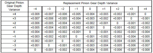
If a new gear set is being installed, note the depth variance etched into both the original and replacement pinion gear. Add or subtract the thickness of the original depth shims to compensate for the difference in the depth variances. Refer to the Depth Variance charts.
Note where Old and New Pinion Marking columns intersect. Intersecting figure represents plus or minus amount needed.
Note the etched number on the face of the drive pinion gear (-1, -2, 0, +1, +2, etc.). The numbers represent thousands of an inch deviation from the standard.
If the number is negative, add that value to the required thickness of the depth shim(s). If the number is positive, subtract that value from the thickness of the depth shim(s). If the number is 0 no change is necessary. Refer to the Pinion Gear Depth Variance Chart.
Fig. 65 Shim Locations
1 - PINION GEAR DEPTH SHIM
2 - DIFFERENTIAL BEARING SHIM-PINION GEAR SIDE
3 - RING GEAR
4 - DIFFERENTIAL BEARING SHIM-RING GEAR SIDE
5 - COLLAPSIBLE SPACER
PINION GEAR DEPTH VARIANCE
PINION DEPTH MEASUREMENT AND ADJUSTMENT
Measurements are taken with pinion cups and pinion bearings installed in housing. Take measurements with a Pinion Gauge Set, Pinion Block 6735, Arbor Discs 6732, and Dial Indicator C-3339 (Fig.
66).
(1) Assemble Pinion Height Block 6739, Pinion Block 6735, and rear pinion bearing onto Screw 6741 (Fig. 66).
(2) Insert assembled height gauge components, rear bearing and screw into axle housing through pinion bearing cups (Fig. 67).
(3) Install front pinion bearing and Cone 6740 hand tight (Fig. 66).
(4) Place Arbor Disc 6732 on Arbor D-115-3 in position in axle housing side bearing cradles (Fig. 68).
Install differential bearing caps on Arbor Discs and tighten cap bolts. Refer to the Torque Specifications in this section.
NOTE: Arbor Discs 6732 have different step diameters to fit other axle sizes. Pick correct size step for axle being serviced.
(5) Assemble Dial Indicator C-3339 into Scooter Block D-115-2 and secure set screw.
Fig. 66 Pinion Gear Depth Gauge Tools-Typical
1 - DIAL INDICATOR
2 - ARBOR
3 - PINION HEIGHT BLOCK
4 - CONE
5 - SCREW
6 - PINION BLOCK
7 - SCOOTER BLOCK
8 - ARBOR DISC
Fig. 67 Pinion Height Block-Typical
1 - PINION BLOCK
2 - PINION HEIGHT BLOCK
1 - ARBOR DISC
2 - PINION BLOCK
3 - ARBOR
4 - PINION HEIGHT BLOCK
(6) Place Scooter Block/Dial Indicator in position in axle housing so dial probe and scooter block are flush against the surface of the pinion height block.
Hold scooter block in place and zero the dial indicator face to the pointer. Tighten dial indicator face lock screw.
(7) With scooter block still in position against the pinion height block, slowly slide the dial indicator probe over the edge of the pinion height block.
Observe how many revolutions counterclockwise the dial pointer travels (approximately 0.125 in.) to the out-stop of the dial indicator.
(8) Slide the dial indicator probe across the gap between the pinion height block and the arbor bar with the scooter block against the pinion height block (Fig. 69). When the dial probe contacts the arbor bar, the dial pointer will turn clockwise. Bring dial pointer back to zero against the arbor bar, do not turn dial face. Continue moving the dial probe to the crest of the arbor bar and record the highest reading.
If the dial indicator can not achieve the zero reading, the rear bearing cup or the pinion depth gauge set is not installed correctly.
(9) Select a shim equal to the dial indicator reading plus the drive pinion gear depth variance number etched in the face of the pinion gear (Fig. 64) using the opposite sign on the variance number. For example, if the depth variance is -2, add +0.002 in. to the dial indicator reading.
(10) Remove the pinion depth gauge components from the axle housing
Fig. 69 Pinion Gear Depth Measurement-Typical
1 - ARBOR
2 - SCOOTER BLOCK
3 - DIAL INDICATOR
Pinion gear depth
Differential bearing preload and gear backlash
Gear contact pattern analysis
Jeep Cherokee Service Manual
- Lubrication and maintenance
- Suspension
- Differential and driveline
- Brakes
- Clutch
- Cooling system
- Battery
- Starting systems
- Charging system
- Ignition system
- Instrument panel systems
- Audio systems
- Horn systems
- Speed control system
- Turn signal and hazard warning systems
- Wiper and washer systems
- Lamps
- Passive restraint systems
- Electrically heated systems
- Power distribution systems
- Power lock systems
- Vehicle theft/security systems
- Power seat systems
- Power window systems
- Power mirror systems
- Chime/buzzer warning systems
- Overhead console systems
- Engine
- Exhaust system
- Frame and bumpers
- Frame
- Fuel system
- Steering
- Transmission and transfer case
- Tires and wheels
- Body
Categories
