 Jeep Cherokee Service ManualTransmission and transfer case » AW-4 automatic transmission » Removal and installation
Speed sensor rotor-speedometer
drive gear
Speed sensor rotor-speedometer drive gear
REMOVAL
(1) Raise vehicle.
(2) Remove components necessary to gain access to rotor and drive gear such as propeller shaft, transfer case, crossmember, and shift linkage.
(3) Disengage wire connector from the output speed sensor.
(4) Remove the bolt holding the output speed sensor to the adapter housing.
(5) Remove the output speed sensor from the adapter housing.
(6) Remove the bolts holding the adapter housing to the transmission case.
(7) Tap the adapter housing at the joint line gently with a rubber mallet to separate the adapter housing from the transmission case.
(8) Remove the adapter housing from the transmission case.
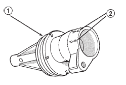
Fig. 52 Index Numbers On Speedometer Pinion Adapter
1 - SENSOR O-RING
2 - SPEEDOMETER ADAPTER
3 - ADAPTER O-RING
4 - SPEEDOMETER PINION
5 - ADAPTER CLAMP
6 - VEHICLE SPEED SENSOR
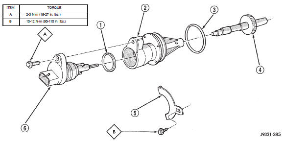
Fig. 51 Speedometer Pinion Adapter Components
1 - SPEEDOMETER ADAPTER
2 - INDEX NUMBER LOCATION
(9) Remove speedometer drive gear snap ring (Fig.
53).
(10) Remove the speedometer drive gear and spacer, if equipped.
(11) Remove rotor from the output shaft. It may be necessary to use a wood dowel or hammer handle (Fig. 54) to gently pry the rotor from the output shaft. Be sure to retrieve the rotor locating key from the output shaft or rotor.
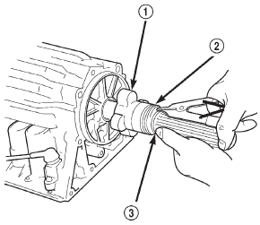
Fig. 53 Removing/Installation Speedometer Drive Gear
1 - ROTOR
2 - SPEEDOMETER DRIVE GEAR
3 - SNAP RING
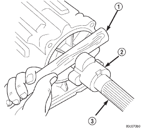
Fig. 54 Removing Speed Sensor Rotor
1 - WOOD DOWEL OR HAMMER HANDLE
2 - ROTOR
3 - OUTPUT SHAFT
INSTALLATION
(1) Clean sealing surfaces of transmission case and extension/adaptor housing.
(2) Install rotor, spacer (if equipped) and drive gear on output shaft. Then install drive gear snap ring (Fig. 53).
(3) Apply 1/8 3/16 inch wide bead of Threebondt Liquid Gasket TB1281, P/N 83504038, to transmission case sealing surface and install extension/ adapter housing on case.
(4) Tighten adaptor housing bolts to 34 N·m (25 ft.
lbs.) torque.
(5) Install components removed to gain access to rotor and drive gear.
Transmission and torque converter
Torque converter
Adapter housing seal
Speed sensor
Speedometer adapter
Speed sensor rotor-speedometer drive gear
Park/neutral position switch
Gearshift cable
Brake transmission shift interlock
Transmission valve body solenoids
Transmission valve body
Transmission control module
Solenoid harness adapter seal
Manual valve shaft seal
Accumulator pistons and springs
Second coast brake servo
Park rod and pawl
Transmission throttle cable
Oil pump seal
Jeep Cherokee Service Manual
- Lubrication and maintenance
- Suspension
- Differential and driveline
- Brakes
- Clutch
- Cooling system
- Battery
- Starting systems
- Charging system
- Ignition system
- Instrument panel systems
- Audio systems
- Horn systems
- Speed control system
- Turn signal and hazard warning systems
- Wiper and washer systems
- Lamps
- Passive restraint systems
- Electrically heated systems
- Power distribution systems
- Power lock systems
- Vehicle theft/security systems
- Power seat systems
- Power window systems
- Power mirror systems
- Chime/buzzer warning systems
- Overhead console systems
- Engine
- Exhaust system
- Frame and bumpers
- Frame
- Fuel system
- Steering
- Transmission and transfer case
- Tires and wheels
- Body
Categories
