 Jeep Cherokee Service ManualStarting systems » Diagnosis and testing
Starter relay
Starter relay
The starter relay (Fig. 13) is located in the Power Distribution Center (PDC), in the engine compartment.
Refer to the fuse and relay layout label affixed to the underside of the PDC cover for starter relay identification and location. Refer to Starting System in the index of this service manual for the location of complete starting system wiring diagrams.
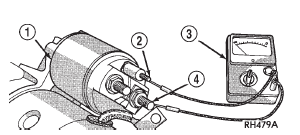
Fig. 11 Continuity Test Between Solenoid Terminal and Field Coil Terminal
- Typical
1 - SOLENOID 2 - SOLENOID TERMINAL 3 - OHMMETER 4 - FIELD COIL TERMINAL
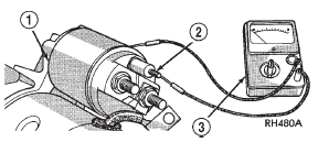
Fig. 12 Continuity Test Between Solenoid Terminal and Solenoid Case -
Typical
1 - SOLENOID 2 - SOLENOID TERMINAL 3 - OHMMETER
RELAY TEST
(1) Remove the starter relay from the PDC. Refer to Starter Relay in the index of this service manual for the location of the proper starter relay removal and installation procedures.
(2) A relay in the de-energized position should have continuity between terminals 87A and 30, and no continuity between terminals 87 and 30. If OK, go to Step 3. If not OK, replace the faulty relay.
(3) Resistance between terminals 85 and 86 (electromagnet) should be 75 6 5 ohms. If OK, go to Step 4. If not OK, replace the faulty relay.
(4) Connect a battery to terminals 85 and 86.
There should now be continuity between terminals 30 and 87, and no continuity between terminals 87A and 30. If OK, perform the Relay Circuit Test that follows. If not OK, replace the faulty relay
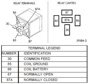
Fig. 13 Starter Relay
RELAY CIRCUIT TEST
(1) The relay common feed terminal cavity (30) is connected to battery voltage and should be hot at all times. If OK, go to Step 2. If not OK, repair the open circuit to the fused B(+) fuse in the PDC as required.
(2) The relay normally closed terminal (87A) is connected to terminal 30 in the de-energized position, but is not used for this application. Go to Step 3.
(3) The relay normally open terminal (87) is connected to the common feed terminal (30) in the energized position. This terminal supplies battery voltage to the starter solenoid field coil. There should be continuity between the cavity for relay terminal 87 and the starter solenoid terminal at all times. If OK, go to Step 4. If not OK, repair the open engine starter motor relay output circuit to the starter solenoid as required.
(4) The coil battery terminal (86) is connected to the electromagnet in the relay. It is energized when the ignition switch is held in the Start position. On vehicles with a manual transmission, the clutch pedal must be blocked in the fully depressed position for this test. Check for battery voltage at the cavity for relay terminal 86 with the ignition switch in the Start position, and no voltage when the ignition switch is released to the On position. If OK, go to Step 5. If not OK with a manual transmission, disconnect the clutch pedal position switch wire harness connector and install a jumper wire between the two cavities in the body half of the connector and check for battery voltage again at the cavity for relay terminal 86. If now OK, replace the faulty clutch pedal position switch. If still not OK with a manual transmission or if not OK with an automatic transmission, check for an open or shorted fused ignition switch output (start) circuit to the ignition switch and repair, as required. If the fused ignition switch output (start) circuit is OK, refer to Ignition Switch and Key Lock Cylinder in the index of this service manual for the location of the proper ignition switch diagnosis and testing procedures.
(5) The coil ground terminal (85) is connected to the electromagnet in the relay. On vehicles with a manual transmission, it is grounded at all times. On vehicles with an automatic transmission, it is grounded through the park/neutral position switch only when the gearshift selector lever is in the Park or Neutral positions. Check for continuity to ground at the cavity for relay terminal 85. If not OK with a manual transmission, repair the open park/neutral position switch sense circuit to ground as required. If not OK with an automatic transmission, check for an open or shorted park/neutral position switch sense circuit to the park/neutral position switch and repair, as required. If the park/neutral position switch sense circuit checks OK, refer to Park/Neutral Position Switch in the index of this service manual for the location of the proper park/neutr
Starting system
Starter motor noise - 2.5L engine
Starter motor
Starter relay
Jeep Cherokee Service Manual
- Lubrication and maintenance
- Suspension
- Differential and driveline
- Brakes
- Clutch
- Cooling system
- Battery
- Starting systems
- Charging system
- Ignition system
- Instrument panel systems
- Audio systems
- Horn systems
- Speed control system
- Turn signal and hazard warning systems
- Wiper and washer systems
- Lamps
- Passive restraint systems
- Electrically heated systems
- Power distribution systems
- Power lock systems
- Vehicle theft/security systems
- Power seat systems
- Power window systems
- Power mirror systems
- Chime/buzzer warning systems
- Overhead console systems
- Engine
- Exhaust system
- Frame and bumpers
- Frame
- Fuel system
- Steering
- Transmission and transfer case
- Tires and wheels
- Body
Categories
