 Jeep Cherokee Service ManualEngine » 2.5L engine » Removal and installation
Timing chain and sprockets
Timing chain and sprockets
The chain drive system ie equipped with a timing chain tensioner which reduces noise and prolongs timing chain life. In addition, it compensates for wear and temperature changes on the valve train for proper engine operation.
REMOVAL
(1) Disconnect negative cable from battery.
(2) Remove the fan and shroud.
(3) Remove the serpentine drive belt.
(4) Remove the crankshaft vibration damper.
(5) Remove the timing case cover.
(6) Rotate crankshaft until the "0" timing mark is closest to and on the center line with camshaft sprocket timing mark (Fig. 65).
(7) Remove the oil slinger from the crankshaft.
(8) Remove the camshaft retaining bolt and remove the sprockets and chain as an assembly (Fig.
66).
(9) To replace the timing chain tensioner, the oil pan must be removed.
INSTALLATION
(1) Turn the tensioner lever to the unlocked (down) position (Fig. 67).
(2) Pull the tensioner block toward the tensioner lever to compress the spring. Hold the block and turn the tensioner lever to the lock position (Fig. 67).
(3) Apply Mopar Silicone Rubber Adhesive Sealant to the keyway in the crankshaft and insert the key.
With the key in the crankshaft keyway, install the crankshaft, camshaft sprockets and timing chain.
Ensure the timing marks on the sprockets are properly aligned (Fig. 65).
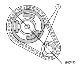
Fig. 65 Crankshaft-Camshaft Alignment
1 - TIMING MARKS
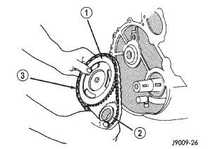
Fig. 66 Camshaft and Crankshaft Sprockets and Chain
1 - CAMSHAFT SPROCKET
2 - CRANKSHAFT SPROCKET
3 - CHAIN
(4) Install the camshaft sprocket retaining bolt and washer. Tighten the bolt to 108 N·m (80 ft. lbs.) torque.
(5) To verify correct installation of the timing chain, turn the crankshaft to position the camshaft sprocket timing mark as shown in (Fig. 68). Count the number of chain pins between the timing marks of both sprockets. There must be 20 pins.
(6) Turn the chain tensioner lever to the unlocked (down) position (Fig. 67).
(7) Install the oil slinger.
(8) Replace the oil seal in the timing case cover.
(9) Install the timing case cover and gasket.
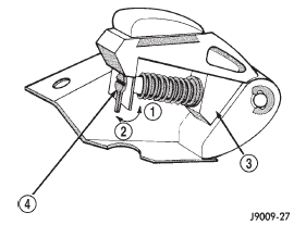
Fig. 67 Loading Timing Chain Tensioner
1 - LOCK
2 - UNLOCK
3 - TENSIONER BLOCK
4 - TENSIONER LEVER
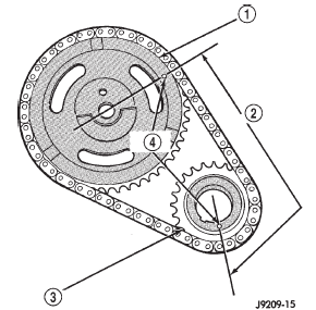
Fig. 68 Verify Sprocket-Chain Installation
1 - CAMSHAFT SPROCKET
2 - 20 PINS
3 - CRANKSHAFT SPROCKET
4 - TIMING MARKS
(10) With the key inserted in the keyway in the crankshaft, install the vibration damper, washer and bolt. Lubricate and tighten the bolt to 108 N·m (80 ft.
lbs.) torque.
(11) Install the fan and shroud.
(12) Connect negative cable to battery.
Engine mounts-front
Engine mount-rear
Engine
Intake manifold
Exhaust manifold
Cylinder head cover
Rocker arms and push rods
Valve spring and seal
Cylinder head
Cylinder head
Hydraulic tappets
Vibration damper
Timing case cover oil seal
Timing case cover
Timing chain and sprockets
Camshaft
Camshaft pin replacement
Camshaft bearings
Crankshaft main bearings
Oil pan
Oil pump
Piston and connecting rod
Rear main oil seal
Jeep Cherokee Service Manual
- Lubrication and maintenance
- Suspension
- Differential and driveline
- Brakes
- Clutch
- Cooling system
- Battery
- Starting systems
- Charging system
- Ignition system
- Instrument panel systems
- Audio systems
- Horn systems
- Speed control system
- Turn signal and hazard warning systems
- Wiper and washer systems
- Lamps
- Passive restraint systems
- Electrically heated systems
- Power distribution systems
- Power lock systems
- Vehicle theft/security systems
- Power seat systems
- Power window systems
- Power mirror systems
- Chime/buzzer warning systems
- Overhead console systems
- Engine
- Exhaust system
- Frame and bumpers
- Frame
- Fuel system
- Steering
- Transmission and transfer case
- Tires and wheels
- Body
Categories
