 Jeep Cherokee Service ManualTransmission and transfer case » NV3550 manual transmission » Removal and installation
Transmission
Transmission
REMOVAL
(1) Shift transmission into first or third gear.
(2) Remove the floor console and shift boot as necessary to access the bottom of the shift lever at the shift tower attachment.
(3) Install nuts on two M6X1.0 bolts and thread the bolts into the threaded holes at the base of the shift lever.
(4) Tighten the nuts equally until the shift lever loosens on the shift tower stub shaft.
(5) Remove the shift lever from the shift tower.
(6) Raise and support vehicle on suitable safety stands.
(7) Support engine with adjustable jack stand.
Position wood block between jack and oil pan to avoid damaging pan.
(8) Remove crossmember/skid plate.
(9) Disconnect necessary exhaust system components.
(10) Remove skid plate, if equipped.
(11) Remove slave cylinder (Fig. 4) from clutch housing.
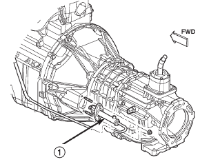
Fig. 4 Slave Cylinder
1 - CLUTCH SLAVE CYLINDER
(12) Mark rear propeller shaft and rear axle yokes for installation alignment (Fig. 5).
(13) Mark front propeller shaft, axle, and transfer case yokes for installation alignment, if equipped.
(14) Remove propeller shaft(s).
(15) Unclip wire harnesses from transmission and transfer case, if equipped.
(16) Disconnect transfer case vent hose, if equipped.
(17) Disengage any wire connectors attached to transmission or transfer case, if equipped, components.
(18) Support transfer case, if equipped, with transmission jack.
(19) Secure transfer case, if equipped, to jack with safety chains.
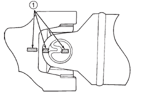
Fig. 5 Marking Propeller Shaft And Axle Yokes
1 - REFERENCE MARKS
(20) Disconnect transfer case shift linkage at transfer case, if equipped.
(21) Remove nuts attaching transfer case to transmission, if equipped.
(22) Remove transfer case, if equipped.
(23) Remove crankshaft position sensor (Fig. 6).
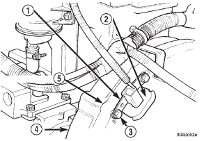
Fig. 6 Crankshaft Position Sensor -2.5 and 4.0L Engine
1 - ENGINE SPEED SENSOR
2 - GROMMET
3 - MOUNTING BOLT(S)
4 - LEFT REAR OF ENGINE
5 - TRANSMISSION
CAUTION: It is important that the crankshaft position sensor be removed prior to transmission removal. The sensor can easily be damaged if left in place during removal operations.
(24) Support engine with adjustable jack stand.
Position wood block between jack and oil pan to avoid damaging pan.
(25) Support transmission with transmission jack.
(26) Secure transmission to jack with safety chains.
(27) Disconnect rear cushion and bracket from transmission.
(28) Remove rear crossmember.
(29) Remove clutch housing-to-engine bolts.
(30) Pull transmission jack rearward until input shaft clears clutch. Then slide transmission out from under vehicle.
(31) Remove clutch release bearing, release fork, and retainer clip.
(32) Remove clutch housing from transmission (Fig. 7).
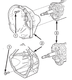
Fig. 7 Clutch Hou
1 - HOUSING-TO-TRANSMISSION BOLTS (46 N·m/34 ft. lbs.)
2 - CLUTCH HOUSING
3 - TRANSMISSION
INSTALLATION
(1) Install clutch housing (Fig. 7) on transmission.
Tighten housing bolts to 46 N·m (34 ft. lbs.) torque.
(2) Lubricate contact surfaces of release fork pivot ball stud and release fork with high temp grease.
(3) Install release bearing, fork, and retainer clip.
(4) Position and secure transmission on transmission jack.
(5) Lightly lubricate pilot bearing and transmission input shaft splines with Mopart high temp grease.
(6) Raise transmission and align transmission input shaft and clutch disc splines. Then slide transmission into place.
(7) Install and tighten clutch housing-to-engine bolts to the appropriate torque: Be sure the housing is properly seated on engine block before tightening bolts.
- Tighten 3/8" diameter bolts to 37 N·m (27 ft.lbs.).
- Tighten 7/16" diameter bolts to 58 N·m (43 ft.lbs.).
- Tighten M12 bolts to 75 N·m (55 ft.lbs.).
(8) Be sure transmission is in first or third gear.
(9) Install rear crossmember. Tighten crossmember- to-frame bolts to 41 N·m (31 ft. lbs.) torque.
(10) Install fasteners to hold rear cushion and bracket to transmission. Then tighten transmissionto- rear support bolts/nuts to 54 N·m (40 ft. lbs.) torque.
(11) Remove support stands from engine and transmission.
(12) Install and connect crankshaft position sensor.
(13) Position transfer case on transmission jack, if equipped.
(14) Secure transfer case to jack with safety chains, if equipped.
(15) Raise transfer case, if equipped, and align transfer case input shaft to the transmission output shaft.
(16) Slide transfer case forward until case is seated on transmission, if necessary.
(17) Install nuts to attach transfer case to transmission, if equipped. Tighten transfer case-to-transmission nuts to 35 N·m (26 ft. lbs.) torque.
(18) Connect transfer case shift linkage at transfer case, if equipped.
(19) Connect transfer case vent hose, if equipped.
(20) Secure wire harnesses in clips/tie straps on transmission and transfer case, if equipped.
(21) Engage wire connectors attached to all necessary transmission or transfer case, if equipped, components.
(22) Install rear propeller shaft slip yoke to transmission or transfer case, if equipped, output shaft.
(23) Align marks on rear propeller shaft and rear axle yokes (Fig. 8).
(24) Install and tighten propeller shaft U-joint clamp bolts to 19 N·m (170 in. lbs.) torque.
(25) Align marks on front propeller shaft, axle, and transfer case yokes, if equipped.
(26) Install and tighten propeller shaft U-joint clamp bolts to 19 N·m (170 in. lbs.) torque.
(27) Install slave cylinder in clutch housing.
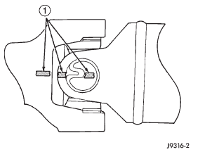
Fig. 8 Align Propeller Shaft And Rear Axle Yokes Alignment Marks
1 - REFERENCE MARKS
(28) Install skid plate, if equipped. Tighten bolts to 42 N·m (31 ft. lbs.) torque. Tighten stud nuts to 17 N·m (150 in. lbs.) torque.
(29) Fill transmission and transfer case, if equipped, with recommended lubricants. Refer to the Lubricant Recommendation sections of the appropriate component for correct fluid.
(30) Lower vehicle.
(31) Install nuts on two M6X1.0 bolts and thread the bolts into the threaded holes at the base of the shift lever.
(32) Tighten the nuts equally until the shift lever will slide over the shift tower stub shaft.
(33) Install the floor console and shift boot.
Transmission
Shift tower
Yoke seal-2WD
Rear housing yoke bushing
Jeep Cherokee Service Manual
- Lubrication and maintenance
- Suspension
- Differential and driveline
- Brakes
- Clutch
- Cooling system
- Battery
- Starting systems
- Charging system
- Ignition system
- Instrument panel systems
- Audio systems
- Horn systems
- Speed control system
- Turn signal and hazard warning systems
- Wiper and washer systems
- Lamps
- Passive restraint systems
- Electrically heated systems
- Power distribution systems
- Power lock systems
- Vehicle theft/security systems
- Power seat systems
- Power window systems
- Power mirror systems
- Chime/buzzer warning systems
- Overhead console systems
- Engine
- Exhaust system
- Frame and bumpers
- Frame
- Fuel system
- Steering
- Transmission and transfer case
- Tires and wheels
- Body
