 Jeep Cherokee Service ManualEngine » 4.0L engine » Service procedures
Valve service
Valve service
Clean all carbon deposits from the combustion chambers, valve ports, valve stems, valve stem guides and head.
Clean all grime and gasket material from the engine cylinder head machined gasket surface.
Inspect for cracks in the combustion chambers and valve ports.
Inspect for cracks on the exhaust seat.
Inspect for cracks in the gasket surface at each coolant passage.
Inspect valves for burned, cracked or warped heads.
Inspect for scuffed or bent valve stems.
Replace valves displaying any damage.
VALVE REFACING
(1) Use a valve refacing machine to reface the intake and exhaust valves to the specified angle.
(2) After refacing, a margin of at least 0.787 mm (0.031 inch) must remain (Fig. 14). If the margin is less than 0.787 mm (0.031 inch), the valve must be replaced.
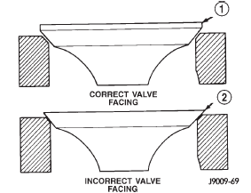
Fig. 14 Valve Facing Margin
1 - VALVE MARGIN
2 - NO MARGIN
VALVE SEAT REFACING
(1) Install a pilot of the correct size in the valve guide bore. Reface the valve seat to the specified angle with a good dressing stone. Remove only enough metal to provide a smooth finish.
(2) Use tapered stones to obtain the specified seat width when required.
(3) Control valve seat runout to a maximum of 0.0635 mm (0.0025 in.) (Fig. 15).
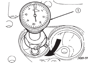
Fig. 15 Measurement of Valve Seat Runout
1 - DIAL INDICATOR
VALVE STEM OIL SEAL REPLACEMENT
Valve stem oil seals are installed on each valve stem to prevent rocker arm lubricating oil from entering the combustion chamber through the valve guide bores. One seal is marked INT (intake valve) and the other is marked EXH (exhaust valve).
Replace the oil seals whenever valve service is performed or if the seals have deteriorated.
VALVE GUIDES
The valve guides are an integral part of the engine cylinder head and are not replaceable.
When the valve stem guide clearance is excessive, the valve guide bores must be reamed oversize. Service valves with oversize stems are available in 0.076 mm (0.003 inch) and 0.381 mm (0.015 inch) increments.
Corresponding oversize valve stem seals are also available and must be used with valves having 0.381 mm (0.015 inch) oversize stems.
NOTE: If the valve guides are reamed oversize, the valve seats must be ground to ensure that the valve seat is concentric to the valve guide.
VALVE STEM-TO-GUIDE CLEARANCE MEASUREMENT
Valve stem-to-guide clearance may be measured by either of the following two methods.
PREFERRED METHOD
(1) Remove the valve from the head.
(2) Clean the valve stem guide bore with solvent and a bristle brush.
(3) Insert a telescoping gauge into the valve stem guide bore approximately 9.525 mm (.375 inch) from the valve spring side of the head (Fig. 16).
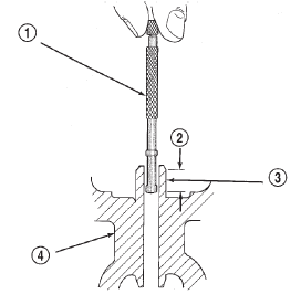
Fig. 16 Measurement of Valve Guide Bore Diameter
1 - GAUGE
2 - 9.525 MM (3/8 INCH)
3 - VALVE STEM GUIDE
4 - CYLINDER HEAD
(4) Remove and measure telescoping gauge with a micrometer.
(5) Repeat the measurement with contacts lengthwise to engine cylinder head.
(6) Compare the crosswise to lengthwise measurements to determine out-of-roundness. If the measurements differ by more than 0.0635 mm (0.0025 in.), ream the guide bore to accommodate an oversize valve stem.
(7) Compare the measured valve guide bore diameter with specifications (7.95-7.97 mm or 0.313-0.314 inch). If the measurement differs from specification by more than 0.076 mm (0.003 inch), ream the guide bore to accommodate an oversize valve stem.
ALTERNATIVE METHOD
(1) Use a dial indicator to measure the lateral movement of the valve stem (stem-to-guide clearance).
This must be done with the valve installed in its guide and just off the valve seat (Fig. 17).
(2) Correct clearance is 0.025-0.0762 mm (0.001-0.003 inch). If indicated movement exceeds the specification ream the valve guide to accommodate an oversize valve stem.
NOTE: Valve seats must be ground after reaming the valve guides to ensure that the valve seat is concentric to the valve guide.
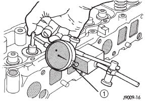
Fig. 17 Measurement of Lateral Movement of Valve
Stem
1 - DIAL INDICATOR
VALVE SPRING TENSION TEST
Use a universal Valve Spring Tester and a torque wrench to test each valve spring for the specified tension value (Fig. 18).
Replace valve springs that are not within specifications.
Valve timing
Valve service
Piston fitting
Piston ring-fitting
Fitting connecting rod bearings
Fitting crankshaft main bearings
Form-in-place gaskets
Engine performance
Honing cylinder bores
Repair damaged or worn threads
Service engine assembly (short block)
Hydrostatic lock
Engine oil service
Jeep Cherokee Service Manual
- Lubrication and maintenance
- Suspension
- Differential and driveline
- Brakes
- Clutch
- Cooling system
- Battery
- Starting systems
- Charging system
- Ignition system
- Instrument panel systems
- Audio systems
- Horn systems
- Speed control system
- Turn signal and hazard warning systems
- Wiper and washer systems
- Lamps
- Passive restraint systems
- Electrically heated systems
- Power distribution systems
- Power lock systems
- Vehicle theft/security systems
- Power seat systems
- Power window systems
- Power mirror systems
- Chime/buzzer warning systems
- Overhead console systems
- Engine
- Exhaust system
- Frame and bumpers
- Frame
- Fuel system
- Steering
- Transmission and transfer case
- Tires and wheels
- Body
Categories
