 Jeep Cherokee Service ManualBrakes » Base brake system » Removal and installation
Wheel cylinder
Wheel cylinder
REMOVAL
(1) Remove wheel and tire assembly.
(2) Remove brake drum.
(3) Disconnect wheel cylinder brake line.
(4) Remove brake shoe return springs and move shoes out of engagement with cylinder push rods.
(5) Remove cylinder attaching bolts and remove cylinder from support plate.
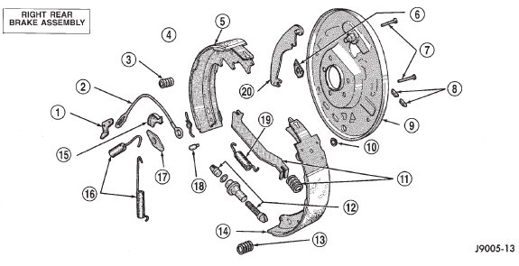
Fig. 34 Drum Brake Components-Typical
1 - ADJUSTER LEVER
2 - ADJUSTER CABLE
3 - HOLDDOWN SPRING AND RETAINERS
4 - ADJUSTER LEVER SPRING
5 - TRAILING SHOE
6 - CYLINDER-TO-SUPPORT SEAL
7 - HOLDDOWN PINS
8 - ACCESS PLUGS
9 - SUPPORT PLATE
10 - CABLE HOLE PLUG
11 - PARK BRAKE STRUT AND SPRING
12 - ADJUSTER SCREW ASSEMBLY
13 - HOLDDOWN SPRING AND RETAINERS
14 - LEADING SHOE
15 - CABLE GUIDE
16 - SHOE RETURN SPRINGS
17 - SHOE GUIDE PLATE
18 - PIN
19 - SHOE SPRING
20 - PARK BRAKE LEVER
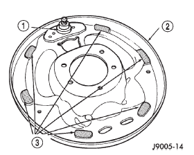
Fig. 35 Shoe Contact Surfaces
1 - ANCHOR PIN
2 - SUPPORT PLATE
3 - SHOE CONTACT SURFACES
INSTALLATION
(1) Apply bead of silicone sealer around cylinder mounting surface of support plate.
(2) Install cylinder mounting bolts and tighten to 20 N·m (15 ft. lbs.).
(3) Connect brake line to cylinder.
(4) Install brake shoe return spring.
(5) Install brake drum.
(6) Install wheel and tire assembly.
(7) Bleed base brake system.
Brake lamp switch
Brake pedal
Combination valve
Master cylinder
Power brake booster
Front disc brake caliper
Front disc brake shoes
Disc brake rotor
Drum brake shoes
Wheel cylinder
Brake support plate
Rear parking brake cables
Parking brake lever
Jeep Cherokee Service Manual
- Lubrication and maintenance
- Suspension
- Differential and driveline
- Brakes
- Clutch
- Cooling system
- Battery
- Starting systems
- Charging system
- Ignition system
- Instrument panel systems
- Audio systems
- Horn systems
- Speed control system
- Turn signal and hazard warning systems
- Wiper and washer systems
- Lamps
- Passive restraint systems
- Electrically heated systems
- Power distribution systems
- Power lock systems
- Vehicle theft/security systems
- Power seat systems
- Power window systems
- Power mirror systems
- Chime/buzzer warning systems
- Overhead console systems
- Engine
- Exhaust system
- Frame and bumpers
- Frame
- Fuel system
- Steering
- Transmission and transfer case
- Tires and wheels
- Body
Categories
