Jeep Cherokee (XJ): 181 FBI pinion shaft seal. 186 FBI pinion shaft seal. Collapsible spacer
181 FBI pinion shaft seal
REMOVAL
- Raise and support the vehicle.
- Remove wheel and tire assemblies.
- Remove brake rotors and calipers. Refer to
Group 5, Brakes, for proper procedures.
- Mark the propeller shaft and pinion yoke for
installation reference.
- Remove the propeller shaft from the yoke.
- Rotate the pinion gear three or four times.
- Measure the amount of torque necessary to
rotate the pinion gear with a (in. lbs.) dial-type
torque wrench. Record the torque reading for installation
reference.
- Using Holder 6958 to hold the pinion yoke,
remove the pinion nut and washer.
- Use Remover C-452 and Wrench C-3281 to
remove the pinion yoke (Fig. 6).
- Use a suitable pry tool or a slide hammer
mounted screw to remove the pinion shaft seal.
INSTALLATION
- Apply a light coating of gear lubricant on the
lip of pinion seal. Install seal with Installer C-3972-A
and Handle C-4171 (Fig. 7).
- Install yoke on the pinion gear with Installer
W-162-D, Cup 8109, and Holder 6958 (Fig. 8).
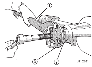
Fig. 6 Pinion Yoke Removal
1 - SPECIAL TOOL C-3281
2 - YOKE
3 - SPECIAL TOOL C-452
 БЮ
Fig. 7 Pinion Seal Installation
БЮ
Fig. 7 Pinion Seal Installation
1 - SPECIAL TOOL C-4171
2 - SPECIAL TOOL C-3972-A
CAUTION: Do not exceed the minimum tightening
torque when installing the pinion yoke retaining nut
at this point. Damage to the pinion bearings may
result.
- Install the pinion washer and a new nut on the
pinion gear. Tighten the nut only enough to
remove the shaft end play.
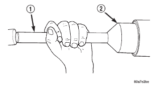
- Tighten pinion nut to 217 N·m (160 ft. lbs.).
- Rotate the pinion shaft using a (in. lbs.) torque
wrench. Rotating torque should be equal to the reading
recorded during removal, plus an additional 0.56
N·m (5 in. lbs.) (Fig. 9).
- If the rotating torque is low, use Holder 6958 to
hold the pinion yoke, and tighten the pinion shaft
nut in 6.8 N·m (5 ft. lbs.) increments until proper
rotating torque is achieved.
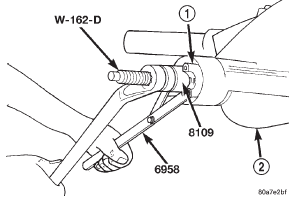
Fig. 8 Pinion Yoke Installation
1 - PINION YOKE
2 - AXLE HOUSING

Fig. 9 Check Pinion Rotation Torque
1 - PINION YOKE
2 - INCH POUND TORQUE WRENCH
- Align the installation reference marks on the
propeller shaft and yoke, and install the propeller
shaft.
- Check and fill the gear lubricant. Refer to the
Lubricant Specifications for gear lubricant requirements.
- Install the brake rotors and calipers. Refer to
Group 5, Brakes, for proper procedures.
- Install wheel and tire assemblies.
- Lower the vehicle.
186 FBI pinion shaft seal
REMOVAL
- Raise and support the vehicle.
- Remove wheel and tire assemblies.
- Remove brake rotors and calipers. Refer to
Group 5, Brakes, for proper procedures.
- Mark the propeller shaft and pinion yoke for
installation reference.
- Remove the propeller shaft from the yoke.
- Rotate the pinion gear three or four times.
- Measure the amount of torque necessary to
rotate the pinion gear with a (in. lbs.) dial-type
torque wrench. Record the torque reading for installation
reference.
- Using Holder 6958 to hold the pinion yoke,
remove the pinion nut and washer.
- Use Remover C-452 and Wrench C-3281 to
remove the pinion yoke (Fig. 10).
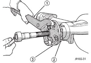
Fig. 10 Pinion Yoke Removal
1 - SPECIAL TOOL C-3281
2 - YOKE
3 - SPECIAL TOOL C-452
- Use a suitable pry tool or a slide hammer
mounted screw to remove the pinion seal.
INSTALLATION
- Apply a light coating of gear lubricant on the
lip of pinion seal. Install seal with Installer C-3972-A
and Handle C-4171 (Fig. 11).
- Install yoke on the pinion gear with Installer
W-162-D, Cup 8109, and Holder 6958 (Fig. 12).
CAUTION: Do not exceed the minimum tightening
torque when installing the pinion yoke retaining nut
at this point. Damage to collapsible spacer or bearings
may result.
Fig. 11 Pinion Seal Installation
1 - SPECIAL TOOL C-4171
2 - SPECIAL TOOL C-3972-A
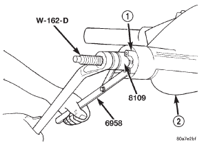
Fig. 12 Pinion Yoke Installation
1 - PINION YOKE
2 - AXLE HOUSING
- Install the pinion washer and a new nut on the
pinion gear. Tighten the nut only enough to
remove the shaft end play.
- Rotate the pinion shaft using a (in. lbs.) torque
wrench. Rotating torque should be equal to the reading
recorded during removal, plus an additional 0.56
N·m (5 in. lbs.) (Fig. 13).
- If the rotating torque is low, use Holder 6958 to
hold the pinion yoke (Fig. 14), and tighten the pinion
shaft nut in 6.8 N·m (5 ft. lbs.) increments until
proper rotating torque is achieved.
CAUTION: If the maximum tightening torque is
reached prior to reaching the required rotating
torque, the collapsible spacer may have been damaged.
Replace the collapsible spacer.
- Align the installation reference marks on the
propeller shaft and yoke and install the propeller
shaft
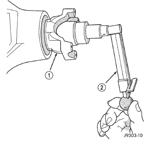
Fig. 13 Check Pinion Rotation Torque
1 - PINION YOKEБЮ
2 - INCH POUND TORQUE WRENCH
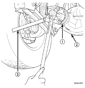
Fig. 14 Tightening Pinion Shaft Nut-Typical
1 - PINION FLANGE
2 - FRONT AXLE
3 - TOOL 6958
- Check and fill the gear lubricant. Refer to the
Lubricant Specifications for gear lubricant requirements.
- Install the brake rotors and calipers. Refer to
Group 5, Brakes, for proper procedures.
- Install wheel and tire assemblies.
- Lower the vehicle.
Collapsible spacer
REMOVAL W/PINION INSTALLED
- Raise and support the vehicle.
- Remove wheel and tire assemblies.
- Remove brake rotors and calipers. Refer to
Group 5, Brakes, for proper procedures.
- Mark the propeller shaft and pinion yoke for
installation reference.
- Remove the propeller shaft from the yoke.
- Rotate the pinion gear three or four times.
- Measure the amount of torque necessary to
rotate the pinion gear with a (in. lbs.) dial-type
torque wrench. Record the torque reading for installation
reference.
- Using Holder 6958 to hold the pinion yoke,
remove the pinion nut and washer.
- Use Remover C-452 and Wrench C-3281 to
remove the pinion yoke (Fig. 15).
- Use a suitable pry tool or a slide hammer
mounted screw, remove the pinion seal.
- Remove the front pinion bearing using a pair
of suitable pick tools to pull the bearing straight off
the pinion gear shaft. It may be necessary to lightly
tap the end of the pinion gear with a rawhide or rubber
mallet if the bearing becomes bound on the pinion
shaft.
- Remove the collapsible spacer.
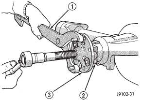
Fig. 15 Pinion Yoke Removal
1 - SPECIAL TOOL C-3281
2 - YOKE
3 - SPECIAL TOOL C-452
REMOVAL W/PINION REMOVED
- Raise and support the vehicle.
- Remove wheel and tire assemblies.
- Remove brake rotors and calipers. Refer to
Group 5, Brakes, for proper procedures.
- Mark the propeller shaft and pinion yoke for
installation reference.
- Remove the propeller shaft from the yoke.
- Rotate the pinion gear three or four times.
- Measure the amount of torque necessary to
rotate the pinion gear with a (in. lbs.) dial-type
torque wrench. Record the torque reading for installation
reference.
- Remove differential assembly from axle housing.
- Using Holder 6958 to hold yoke, remove the
pinion nut and washer.
- Using Remover C-452 and Wrench C-3281,
remove the pinion yoke from pinion shaft (Fig. 15).
- Remove the pinion gear from housing (Fig.
16). Catch the pinion with your hand to prevent it
from falling and being damaged.
- Remove collapsible spacer from pinion shaft.
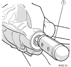
Fig. 16 Remove Pinion Gear
1 - RAWHIDE HAMMER
INSTALLATION
- Install a new collapsible preload spacer on pinion
shaft (Fig. 17).
- If pinion gear was removed, install pinion gear
in housing.
- Install pinion front bearing, if necessary.
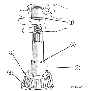
Fig. 17 Collapsible Preload Spacer
1 - COLLAPSIBLE SPACER
2 - SHOULDER
3 - PINION GEAR
4 - OIL SLINGER
5 - REAR BEARING
- Apply a light coating of gear lubricant on the
lip of pinion seal. Install seal with Installer C-3972-A
and Handle C-4171 (Fig. 18), if necessary.
Fig. 18 Pinion Seal Installation
1 - SPECIAL TOOL C-4171
2 - SPECIAL TOOL C-3972-A
- Install yoke with Installer W-162-D, Cup 8109,
and holder 6958 (Fig. 19).
- If the original pinion bearings are being used,
install differential assembly and axle shafts, if necessary.
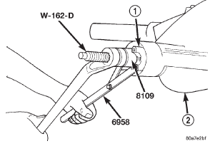
Fig. 19 Pinion Yoke Installation
NOTE: If new pinion bearings were installed, do not
install the differential assembly and axle shafts until
after the pinion bearing preload and rotating torque
are set.
- Install the pinion washer and a new nut on the
pinion gear. Tighten the nut to 217 N·m (160 ft. lbs.)
minimum. Do not over-tighten. Maximum torque is
353 N·m (260 ft. lbs.).
CAUTION: Never loosen pinion gear nut to
decrease pinion gear bearing rotating torque and
never exceed specified preload torque. If preload
torque is exceeded, a new collapsible spacer must
be installed. The torque sequence will then have to
be repeated.
- Using yoke holder 6958 and a torque wrench
set at 353 N·m (260 ft. lbs.), crush collapsible spacer
until bearing end play is taken up (Fig. 20). If more
than 353 N·m (260 ft. lbs.) is needed to begin to collapse
the spacer, the spacer is defective and must be
replaced.
- Slowly tighten the nut in 6.8 N·m (5 ft. lbs.)
increments until the rotating torque is achieved.
Measure the rotating torque frequently to avoid over
crushing the collapsible spacer (Fig. 21).
- Check rotating torque with an inch pound
torque wrench (Fig. 21). The torque necessary to
rotate the pinion gear should be:
- Original Bearings - The reading recorded during
removal, plus an additional 0.56 N·m (5 in. lbs.).
- New Bearings - 1.5 to 4 N·m (15 to 35 in. lbs.).
- Install differential assembly and axle shafts, if
necessary.
- Align marks made previously on yoke and
propeller shaft and install propeller shaft.
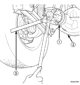
Fig. 20 Tightening Pinion Nut
1 - PINION FLANGE
2 - FRONT AXLE
3 - TOOL 6958
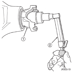
Fig. 21 Check Pinion Gear Rotation Torque-Typical
1 - PINION YOKE
2 - INCH POUND TORQUE WRENCH
- Install brake rotors and calipers. Refer to
Group 5, Brakes, for proper procedures.
 БЮ
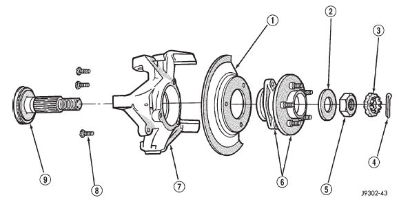
Fig. 22 Hub, Knuckle and Axle Shaft
БЮ
Fig. 22 Hub, Knuckle and Axle Shaft
1 - BRAKE SHIELD
2 - WASHER
3 - RETAINER
4 - COTTER PIN
5 - NUT
6 - HUB AND BEARING ASSEMBLY
7 - STEERING KNUCKLE
8 - BOLT
9 - TONE WHEEL (ABS)
- Add gear lubricant, if necessary. Refer to
Lubricant Specifications of this section for lubricant
requirements.
- Install wheel and tire assemblies.
- Lower vehicle.
Other materials:
Off-road driving tips
When To Use 4WD LOW Range
When off-road driving, shift to 4WD LOW for additional
traction and control on slippery or difficult terrain,
ascending or descending steep hills, and to increase
low-speed pulling power (refer to "All Wheel Drive and
Four-Wheel Drive Operation" in this section for furt ...
 Drive axle assembly. Tube axle assembly. Axle shaft-cardan U-joint
 Hub bearing and axle shaft. Steering knuckle and ball studs. Differential