Jeep Cherokee (XJ): Accumulator. Pistons. Front clutch
DESCRIPTION The accumulator (Fig. 36) is a hydraulic device
that has the sole purpose of cushioning the application
of a band or clutch. The accumulator consists of
a dual-land piston and a spring located in a bore in
the transmission case. OPERATION Line pressure is directed between the lands of the
piston (Fig. 37), bottoming it against the accumulator
plate. The accumulator stays in this position after
the transmission is placed into a Drive position.
When the 1-2 upshift occurs (Fig. 38), line pressure is directed to the large
end of the piston and then to
the kickdown servo. As the line pressure reaches the
accumulator, the combination of spring pressure and
line pressure forces the piston away from the accumulator
plate. This causes a balanced pressure situation,
which results in a cushioned band application.
After the kickdown servo has become immovable, line
pressure will finish pushing the accumulator up into
its bore. When the large end of the accumulator piston
is seated in its bore, the band or clutch is fully
applied.
1 - ACCUMULATOR PISTON
1 - 1-2 GOVERNOR PLUG NOTE: The accumulator is shown in the inverted
position for illustrative purposes.
1 - BOTTOM IN BORE DESCRIPTION There are several sizes and types of pistons used in
an automatic transmission. Some pistons are used to
apply clutches, while others are used to apply bands.
They all have in common the fact that they are round or
circular in shape, located within a smooth walled cylinder,
which is closed at one end and converts fluid pressure
into mechanical movement. The fluid pressure
exerted on the piston is contained within the system
through the use of piston rings or seals. OPERATION The principal which makes this operation possible is
known as Pascal's Law. Pascal's Law can be stated as:
"Pressure on a confined fluid is transmitted equally in
all directions and acts with equal force on equal areas." PRESSURE Pressure (Fig. 39) is nothing more than force (lbs.)
divided by area (in or ft.), or force per unit area.
Given a 100 lb. block and an area of 100 sq. in. on
the floor, the pressure exerted by the block is: 100
lbs. 100 in or 1 pound per square inch, or PSI as it is
commonly referred to.
PRESSURE ON A CONFINED FLUID Pressure is exerted on a confined fluid (Fig. 40) by
applying a force to some given area in contact with the
fluid. A good example of this is a cylinder filled with
fluid and equipped with a piston that is closely fitted to
the cylinder wall. If a force is applied to the piston,
pressure will be developed in the fluid. Of course, no pressure will be created
if the fluid is not confined. It
will simply "leak" past the piston. There must be a
resistance to flow in order to create pressure. Piston
sealing is extremely important in hydraulic operation.
Several kinds of seals are used to accomplish this
within a transmission. These include but are not limited
to O-rings, D-rings, lip seals, sealing rings, or
extremely close tolerances between the piston and the
cylinder wall. The force exerted is downward (gravity),
however, the principle remains the same no matter
which direction is taken. The pressure created in the
fluid is equal to the force applied, divided by the piston
area. If the force is 100 lbs., and the piston area is 10
sq. in., then the pressure created equals 10 PSI.
Another interpretation of Pascal's Law is that regardless
of container shape or size, the pressure will be
maintained throughout, as long as the fluid is confined.
In other words, the pressure in the fluid is the same
everywhere within the container.
FORCE MULTIPLICATION Using the 10 PSI example used in the illustration
(Fig. 41), a force of 1000 lbs. can be moved with a
force of only 100 lbs. The secret of force multiplication
in hydraulic systems is the total fluid contact
area employed. The illustration, (Fig. 41), shows an
area that is ten times larger than the original area.
The pressure created with the smaller 100 lb. input
is 10 PSI. The concept "pressure is the same everywhere"
means that the pressure underneath the
larger piston is also 10 PSI. Pressure is equal to the
force applied divided by the contact area. Therefore,
by means of simple algebra, the output force may be
found. This concept is extremely important, as it is
also used in the design and operation of all shift
valves and limiting valves in the valve body, as well
as the pistons, of the transmission, which activate
the clutches and bands. It is nothing more than
using a difference of area to create a difference in
pressure to move an object.
PISTON TRAVEL The relationship between hydraulic lever and a
mechanical lever is the same. With a mechanical
lever it's a weight-to-distance output rather than a
pressure-to-area output. Using the same forces and
areas as in the previous example, the smaller piston
(Fig. 42) has to move ten times the distance required
to move the larger piston one inch. Therefore, for
every inch the larger piston moves, the smaller piston
moves ten inches. This principle is true in other
instances also. A common garage floor jack is a good
example. To raise a car weighing 2000 lbs., an effort
of only 100 lbs. may be required. For every inch the
car moves upward, the input piston at the jack handle
must move 20 inches downward.
DESCRIPTION The front clutch assembly (Fig. 43) is composed of
the front clutch retainer, pressure plate, four clutch
plates, four driving discs, piston, piston return
spring, return spring retainer, and snap rings. The
front clutch is the forwardmost component in the
transmission geartrain and is directly behind the oil
pump and is considered a driving component.
NOTE: The number of discs and plates may vary
with each engine and vehicle combination. OPERATION To apply the clutch, pressure is applied between
the clutch retainer and piston. The fluid pressure is
provided by the oil pump, transferred through the
control valves and passageways, and enters the
clutch through the hub of the reaction shaft support.
With pressure applied between the clutch retainer
and piston, the piston moves away from the clutch
retainer and compresses the clutch pack. This action
applies the clutch pack, allowing torque to flow
through the input shaft into the driving discs, and
into the clutch plates and pressure plate that are
lugged to the clutch retainer. The waved snap ring is
used to cushion the application of the clutch pack. In
some transmissions, the snap ring is selective and
used to adjust clutch pack clearance.
When pressure is released from the piston, the
spring returns the piston to its fully released position
and disengages the clutch. The release spring also
helps to cushion the application of the clutch assembly.
When the clutch is in the process of being
released by the release spring, fluid flows through a
vent and one-way ball-check-valve located in the
clutch retainer. The check-valve is needed to eliminate
the possibility of plate drag caused by centrifugal
force acting on the residual fluid trapped in the
clutch piston retainer.
1 - RETAINER HUB SEALAccumulator
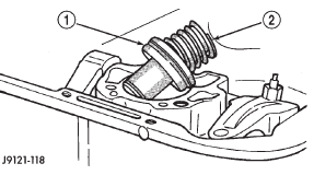
Fig. 36 Accumulator
2 - PISTON SPRING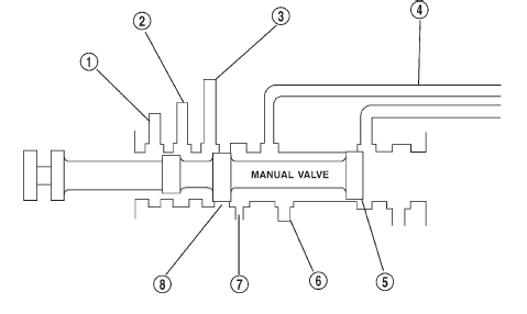
Fig. 35 Manual Valve
2 - 2-3 GOVERNOR PLUG
3 - GOVERNOR REAR CLUTCH ACCUMULATOR
4 - THROTTLE VALVE
5 - LAND #1
6 - PUMP
7 - PRESSURE REGULATOR
8 - LAND #2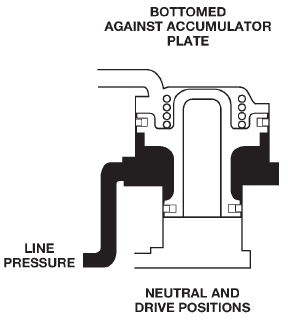
Fig. 37 Accumulator in Neutral and Drive Positions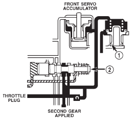
Fig. 38 Accumulator in Second Gear Position
2 - SHUTTLE VALVEPistons
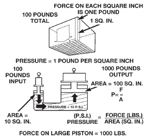
Fig. 39 Force and Pressure Relationship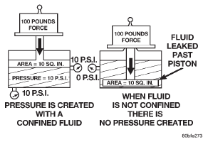
Fig. 40 Pressure on a Confined Fluid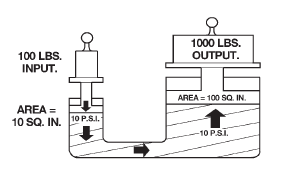
Fig. 41 Force Multiplication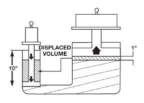
Fig. 42 Piston TravelFront clutch
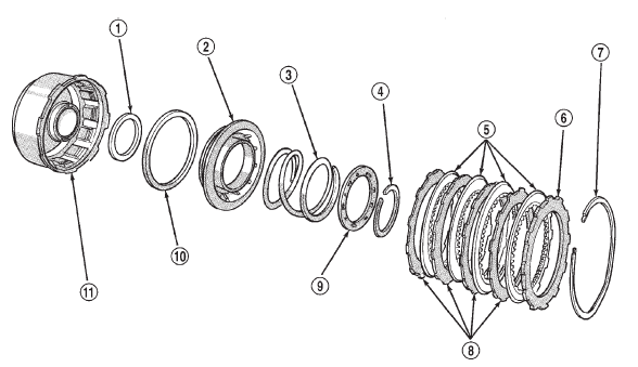
Fig. 43 Front Clutch
2 - CLUTCH PISTON
3 - PISTON SPRING
4 - SPRING RETAINER SNAP RING
5 - CLUTCH DISCS
6 - PRESSURE PLATE
7 - SNAP RING (WAVED)
8 - CLUTCH PLATES
9 - SPRING RETAINER
10 - PISTON SEAL
11 - FRONT CLUTCH RETAINER

 Rear clutch. Overrunning clutch. Planetary gearset
Other materials:
Service procedures
LUBRICANT CHANGE
Raise and support the vehicle.
Remove the lubricant fill hole plug from the
differential housing cover.
Remove the differential housing cover and
drain the lubricant from the housing.
Clean the housing cavity with a flushing oil,
light engine ...