Jeep Cherokee (XJ): Adapter housing. Speedometer adapter. Park/neutral position switch
REMOVAL (1) Hoist and support vehicle on safety stands.
(2) Support transmission with a suitable lifting
device.
(3) Remove transmission skid plate. Refer to
Group 13, Frame and Bumpers, for proper procedure.
1 - REMOVER 6957
1 - SPECIAL TOOL C-4171 (4) Remove propeller shafts. Refer to Group 3, Differential
and Driveline, for proper procedure.
(5) Remove transfer case.
(6) Remove bolts holding adapter housing to transmission
case (Fig. 75).
(7) Separate adapter housing from transmission.
(8) Slide adapter housing rearward and off output
shaft (Fig. 75). INSTALLATION Clear gasket material from sealing surfaces on
adapter housing and rear of transmission. Replace
output shaft bearing, if necessary.
(1) Install new rear seal in adapter housing. Use
Tool Handle C-4171 and Seal Installer C-3860-A to
install seal.
(2) Place adapter housing gasket in position on
rear of transmission.
(3) Slide adapter housing forward and over output
shaft (Fig. 75).
1 - TRANSMISSION (4) Guide park shaft into park sprag and push
adapter housing forward until rod passes through
opening behind sprag. It may be necessary to use a
wire to hold sprag to the side for rod to pass through.
(5) Install bolts to hold adapter housing to rear of
transmission.
(6) Install transfer case.
(7) Install propeller shafts.
(8) Install rear transmission mount and skid plate.
(9) Lower vehicle and verify transmission fluid
level. Add fluid as necessary. Rear axle gear ratio and tire size determine speedometer
pinion requirements. REMOVAL (1) Raise vehicle.
(2) Disconnect wires from vehicle speed sensor.
(3) Remove adapter clamp and screw (Fig. 76).
(4) Remove speed sensor and speedometer adapter
as assembly.
(5) Remove speed sensor retaining screw and
remove sensor from adapter.
(6) Remove speedometer pinion from adapter.
(7) Inspect sensor and adapter O-rings (Fig. 76).
Remove and discard O-rings if worn or damaged.
(8) Inspect terminal pins in speed sensor. Clean
pins with Mopart electrical spray cleaner if dirty or
oxidized. Replace sensor if faulty, or pins are loose,
severely corroded, or damaged. INSTALLATION (1) Thoroughly clean adapter flange and adapter
mounting surface in housing. Surfaces must be clean for proper adapter alignment
and speedometer operation.
(2) Install new O-rings on speed sensor and speedometer
adapter if necessary (Fig. 76).
(3) Lubricate sensor and adapter O-rings with
transmission fluid.
(4) Install vehicle speed sensor in speedometer
adapter. Tighten sensor attaching screw to 2-3 N·m
(15-27 in. lbs.) torque.
(5) Install speedometer pinion in adapter.
(6) Count number of teeth on speedometer pinion.
Do this before installing assembly in housing. Then
lubricate pinion teeth with transmission fluid.
(7) Note index numbers on adapter body (Fig. 77).
These numbers will correspond to number of teeth on
pinion.
(8) Install speedometer assembly in housing.
(9) Rotate adapter until required range numbers
are at 6 o'clock position. Be sure range index numbers
correspond to number of teeth on pinion gear.
(10) Install speedometer adapter clamp and retaining
screw. Tighten clamp screw to 10-12 N·m (90-110
in. lbs.) torque.
(11) Connect wires to vehicle speed sensor.
(12) Lower vehicle and top off transmission fluid
level, if necessary.
1 - SPEEDOMETER ADAPTER REMOVAL (1) Raise vehicle and position drain pan under
switch.
(2) Disconnect switch wires.
(3) Remove switch from case.
1 - SENSOR O-RING INSTALLATION (1) Move shift lever to Park and Neutral positions.
Verify that switch operating lever fingers are centered
in switch opening in case (Fig. 78).
1 - NEUTRAL CONTACT 2) Install new seal on switch and install switch in
case. Tighten switch to 34 N·m (25 ft. lbs.) torque.
(3) Test continuity of new switch with 12V test
lamp.
(4) Connect switch wires and lower vehicle.
(5) Top off transmission fluid level.Adapter housing
Fig. 73 Bushing Removal-Typical
2 - EXTENSION HOUSING BUSHING
Fig. 74 Extension Housing Seal Installation
2 - SPECIAL TOOL C-3995-A
Fig. 75 Adapter Housing
2 - GASKET
3 - ADAPTER HOUSINGSpeedometer adapter
Fig. 77 Index Numbers On Speedometer Pinion Adapter
2 - INDEX NUMBER LOCATIONPark/neutral position switch
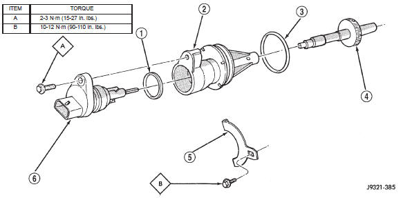
Fig. 76 Speedometer Pinion Adapter Components
2 - SPEEDOMETER ADAPTER>
3 - ADAPTER O-RING>
4 - SPEEDOMETER PINION>
5 - ADAPTER CLAMP>
6 - VEHICLE SPEED SENSOR
Fig. 78 Park/Neutral Position Switch
2 - MANUAL LEVER AND SWITCH PLUNGER IN REVERSE
POSITION
3 - PARK CONTACT
4 - SWITCH
 Torque converter. Yoke seal replacement. Extension housing bushing
 Gearshift cable. Brake transmission shift interlock. Valve body
Other materials:
Off-road driving tips
When To Use 4WD LOW Range
When off-road driving, shift to 4WD LOW for additional
traction and control on slippery or difficult terrain,
ascending or descending steep hills, and to increase
low-speed pulling power (refer to "All Wheel Drive and
Four-Wheel Drive Operation" in this section for furt ...