Jeep Cherokee (XJ): Camshaft bearings. Crankshaft main bearings. Oil pan
The camshaft rotates within four steel-shelled,
babbitt-lined bearings that are pressed into the cylinder
block and then line reamed. The camshaft
bearing bores and bearing diameters are not the
same size. They are stepped down in 0.254 mm
(0.010 inch) increments from the front bearing (largest)
to the rear bearing (smallest). This permits easier
removal and installation of the camshaft. The
camshaft bearings are pressure lubricated.
NOTE: It is not advisable to attempt to replace
camshaft bearings unless special removal and
installation tools are available, such as recommended
tool 8544 Camshaft Bushing Remover
Installer.
Camshaft end play is maintained by the load
placed on the camshaft by the oil pump and distributor
drive gear. The helical cut of the gear holds the
camshaft sprocket thrust face against the cylinder
block face. REMOVAL (1) Disconnect negative cable from battery.
(2) Remove the spark plugs.
(3) Raise the vehicle.
(4) Remove the oil pan and oil pump.
(5) Remove only one main bearing cap and lower
insert at a time (Fig. 76).
(6) Remove the lower insert from the bearing cap.
(7) Remove the upper insert by LOOSENING (DO
NOT REMOVE) all of the other bearing caps. Now
insert a small cotter pin tool in the crankshaft journal
oil hole. Bend the cotter pin as illustrated to fabricate
the tool (Fig. 77). With the cotter pin tool in
place, rotate the crankshaft so that the upper bearing
insert will rotate in the direction of its locking
tab. Because there is no hole in the No.3 main journal,
use a tongue depressor or similar soft-faced tool to remove the bearing insert
(Fig. 77). After moving
the insert approximately 25 mm (1 inch), it can be
removed by applying pressure under the tab.
1 - CONNECTING ROD JOURNAL (8) Using the same procedure described above,
remove the remaining bearing inserts one at a time
for inspection. INSTALLATION (1) Lubricate the bearing surface of each insert
with engine oil.
(2) Loosen all the main bearing caps. Install the
main bearing upper inserts.
(3) Install the lower bearing inserts into the main
bearing caps.
(4) Install the main bearing cap(s) and lower
insert(s).
(5) Clean the rear main bearing cap (No.5) mating
surfaces.
(6) Apply Mopart Gasket Maker, or equivalent on
the rear bearing cap (Fig. 78). The bead should be 3
mm (0.125 in) thick. DO NOT apply Mopart Gasket
Maker, or equivalent to the lip of the seal.
(7) Install the rear main bearing cap. DO NOT
strike the cap more than twice for proper engagement.
(8) Tighten the bolts of caps 1, 3, 4 and 5 to 54
N·m (40 ft. lbs.) torque. Now tighten these bolts to 95
N·m (70 ft. lbs.) torque. Finally, tighten these bolts to
108 N·m (80 ft. lbs.) torque.
1 - COTTER PIN
1 - MOPART GASKET MAKER (OR EQUIVALENT) (9) Push the crankshaft forward and backward.
Load the crankshaft front or rear and tighten cap
bolt No.2 to 54 N·m (40 ft. lbs.) torque. Then tighten
to 95 N·m (70 ft. lbs.) torque and finally tighten to
108 N·m (80 ft. lbs.) torque.
(10) Rotate the crankshaft after tightening each
main bearing cap to ensure the crankshaft rotates
freely.
(11) Check crankshaft end play. Crankshaft end
play is controlled by the thrust bearing which is
flange and installed at the No.2 main bearing position.
(a) Attach a magnetic base dial indicator to the
cylinder block at either the front or rear of the
engine.
(b) Position the dial indicator rod so that it is
parallel to the center line of the crankshaft.
(c) Pry the crankshaft forward, position the dial
indicator to zero.
(d) Pry the crankshaft forward and backward.
Note the dial indicator readings. End play is the
difference between the high and low measurements
(Fig. 79). Correct end play is 0.038-0.165 mm
(0.0015-0.0065 inch). The desired specifications are
0.051-0.064 mm (0.002-0.0025 inch).
(e) If end play is not within specification, inspect
crankshaft thrust faces for wear. If no wear is
apparent, replace the thrust bearing and measure
end play. If end play is still not within specification,
replace the crankshaft.
1 - DIAL INDICATOR (12) If the crankshaft was removed, install the
crankshaft into the cylinder block (refer to Cylinder
Block - Assemble).
(13) Install the oil pan.
(14) Install the drain plug. Tighten the plug to 34
N·m (25 ft. lbs.) torque.
(15) Install new rearmain seal. Refer to Rear Main
Seal in this section.
(16) Lower the vehicle.
(17) Install the spark plugs. Tighten the plugs to
37 N·m (27 ft. lbs.) torque.
(18) Fill the oil pan with engine oil to the safe
mark on the dipstick level.
(19) Connect negative cable to battery. REMOVAL (1) Disconnect negative cable from battery.
(2) Raise the vehicle.
(3) Remove the oil pan drain plug and drain the
engine oil.
(4) Disconnect the exhaust pipe at the engine
exhaust manifold.
(5) Disconnect the exhaust hanger at the catalytic
converter and lower the pipe.
(6) Remove the engine starter motor.
(7) Remove the flywheel/torque converter housing
access cover.
(8) Position a jack stand directly under the engine
vibration damper.
(9) Place a piece of wood (2 x 2) between the jack
stand and the engine vibration damper.
(10) Remove the engine mount through bolts.
(11) Using the jack stand, raise the engine until
adequate clearance is obtained to remove the oil pan.
(12) If equipped, disconnect the transmission
cooler lines and oxygen sensor harness from oil pan
mounting studs.
(13) Remove the oil pan bolts and studs. Carefully
remove the oil pan and gasket. INSTALLATION (1) Clean the block and pan gasket surfaces.
(2) Fabricate 4 alignment dowels from 1/4 x 1 1/2
inch bolts. Cut the head off the bolts and cut a slot
into the top of the dowel. This will allow easier
installation and removal with a screwdriver (Fig. 80).
(3) Install two dowels in the timing case cover.
Install the other two dowels in the cylinder block
(Fig. 81).
(4) Apply Mopart Silicone Adhesive Sealant onto
the cylinder block in four location as shown (Fig. 82)
(5) Slide the one-piece gasket over the dowels and
onto the block and timing case cover.
(6) Position the oil pan over the dowels and onto
the gasket.
(7) Install the 1/4 inch oil pan bolts. Tighten these
bolts to 9.5 N·m (84 in. lbs.) torque. Install the 5/16 inch oil pan bolts (Fig.
83). Tighten these bolts to 15
N·m (132 in. lbs.) torque.
1 - 1/488 3 1 1/288 BOLT
1 - 5/1688 HOLES (8) Remove the dowels. Install the remaining 1/4
inch oil pan bolts. Tighten these bolts to 9.5 N·m (84
in. lbs.) torque.
(9) Lower the engine until it is properly located on
the engine mounts.
(10) Install the through bolts and tighten the nuts.
(11) Lower the jack stand and remove the piece of
wood.
(12) Install the flywheel and torque converter
housing access cover.
(13) Install the engine starter motor.
(14) Connect the exhaust pipe to the hanger and to
the engine exhaust manifold.
1 - SEALER LOCATIONS
1 - OIL PAN (15) Install the oil pan drain plug (Fig. 83).
Tighten the plug to 34 N·m (25 ft. lbs.) torque.
(16) Lower the vehicle.
(17) Connect negative cable to battery.
(18) Fill the oil pan with engine oil to the specified
level.
WARNING: USE EXTREME CAUTION WHEN THE
ENGINE IS OPERATING. DO NOT STAND IN A
DIRECT LINE WITH THE FAN. DO NOT PUT YOUR
HANDS NEAR THE PULLEYS, BELTS OR FAN. DO
NOT WEAR LOOSE CLOTHING.
(19) Start the engine and inspect for leaks.Camshaft bearings
Crankshaft main bearings
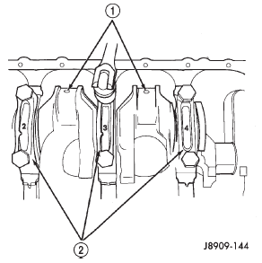
Fig. 76 Removing Main Bearing Caps and Lower Inserts
2 - MAIN BEARING CAPS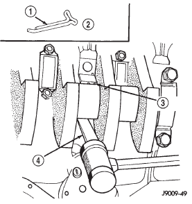
Fig. 77 Removing Upper Inserts
2 - FABRICATED TOOL
3 - BEARING INSERT
4 - TONGUE DEPRESSOR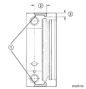
Fig. 78 Location of MoparT Gasket Maker
2 - 19 mm (.75 IN)
3 - 6 mm (0.025 IN)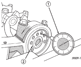
Fig. 79 Crankshaft End Play Measurement
2 - CRANKSHAFTOil pan
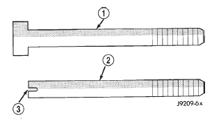
Fig. 80 Fabrication of Alignment Dowels
2 - DOWEL
3 - SLOT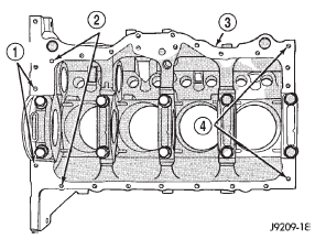
Fig. 81 Position of Dowels in Cylinder Block
2 - DOWEL HOLES
3 - CYLINDER BLOCK
4 - 5/1688 HOLES
Fig. 82 Location of MoparT Silicone Adhesive Sealant on Cylinder Block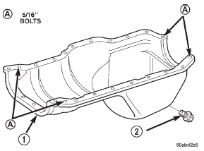
Fig. 83 Position of 5/16 inch Oil Pan Bolts
2 - OIL PAN DRAIN PLUG

 Oil pump. Piston and connecting rod. Rear main oil seal
Other materials:
Compressor clutch relay. Dual function high pressure
switch/high pressure cut-off
switch. Heater performance
Compressor clutch relay
RELAY TEST
The compressor clutch relay (Fig. 8) is located in
the Power Distribution Center (PDC). Refer to the
PDC label for relay identification and location.
Remove the relay from the PDC to perform the following
tests:
(1) A relay in the de-energized position shou ...