Jeep Cherokee (XJ): Cleaning and inspection. Adjustments. Specifications
TRANSMISSION PARTS CLEANING AND
INSPECTION Clean the transmission components with solvent
and dry them with compressed air only. Do not use
shop towels or rags.
Blow compressed air through all oil feed passages
and channels to be sure they are clear. Inspect the
transmission components for wear and damage.
Replace components that are damaged or worn
beyond the limits specified in the individual overhaul
procedures.
Replace all O-rings, gaskets and seals. These components
are not reusable. Also replace any snap ring
that is distorted or damaged.
During overhaul assembly operations, lubricate the
transmission components with Mopar Mercony automatic
transmission fluid or petroleum jelly as indicated.
Petroleum jelly should be used to prelubricate
thrust bearings, washers and races. It can also be
used to hold parts in position during assembly.
Soak replacement clutch and brake pack
components in transmission fluid for at least 30
minutes before installation. Check adjustment by starting the engine in Park
and Neutral. Adjustment is OK if the engine starts
only in these positions. Adjustment is incorrect if the
engine starts in one but not both positions. If the
engine starts in any position other than Park or Neutral,
or if the engine will not start at all, the park/
neutral position switch may be faulty. Gearshift Adjustment Procedure (1) Shift transmission into Park.
(2) Raise vehicle.
(3) Release cable adjuster clamp (at transmission
end of cable) to unlock cable.
(4) Unsnap cable from cable mounting bracket on
transmission (Fig. 300).
(5) Slide cable eyelet off transmission shift lever.
(6) Verify transmission shift lever is in Park
detent by moving lever fully rearward. Last rearward
detent is Park position.
(7) Verify positive engagement of transmission
park lock by attempting to rotate propeller shaft.
Shaft will not rotate when park lock is engaged.
(8) Slide cable eyelt onto transmission shift lever.
(9) Snap shift cable adjuster into mounting
bracket on transmission.
(10) Lock shift cable by pressing cable adjuster
clamp down until it snaps into place.
(11) Lower vehicle and check engine starting.
Engine should start only in Park and Neutral.
1 - THROTTLE VALVE CABLE (1) Shift transmission into PARK.
(2) Remove shift lever bezel and console screws.
Raise bezel and console for access to cable.
(3) Pull cable lock button up to release cable (Fig.
301).
(4) Turn ignition switch to LOCK position.
(5) Use a spacer to create a one millimeter gap
between the shifter pawl and top of the shift gate.
(6) Pull cable forward. Then release cable and
press cable lock button down until it snaps in place.
(7) Check adjustment as follows:
(a) Check movement of release shift handle button
(floor shift) or release lever (column shift). You
should not be able to press button inward or move
column lever.
(b) Turn ignition switch to RUN position.
(c) Shifting out of park should not be possible.
(d) Apply the brake and attempt to shift out of
PARK. Shifting should be possible.
(e) While the transmission is shifted out of
PARK, release the brake and attempt to shift through all gears. Release the
shift button at least
once during this procedure. The ignition key should
not go to the LOCK position.
1 - PARK LOCK CABLE (f) Return transmission to the PARK position
without applying the brake.
(8) Move shift lever back to PARK and check ignition
switch operation. You should be able to turn
switch to LOCK position and shift lever release button/
lever should not move. (1) Shift transmission into Park, shut engine off
and raise hood.
(2) Press cable release button (Fig. 302).
(3) Push cable conduit back into cable sheath as
far as possible (Fig. 303).
(4) Rotate lever on throttle body to wide open
throttle position. Cable will ratchet to correct adjustment
point as lever is rotated (Fig. 303).
1 - CONDUIT
1 - RELEASE BUTTON AW-4 AUTOMATIC TRANSMISSION AW-4 GENERAL SPECIFICATIONS Gear Ratios: First . . . . . . . . . . . . . . . . . . . . . . . . . . . . . 2.804:1 Transmission Fluid . . Jeep automatic transmission
fluid or DEXRONt II Test Specifications Stall Speed: In D Range and Reverse . . . . . . . 2100-2400 rpm Time Lag Test: Engagement in D Range . . . . . . . . . . 1.2 seconds Transmission Fluid Normal Operating Temperature . . . . . . . . . . . . 50-80C (122-176F) AW-4 CLUTCH DISC AND PLATE THICKNESS
AW-4 OIL PUMP WEAR LIMITS Drive Gear Tip Clearance: . . . . . . . . . . . . . . . . . . . . . . . . . . . . . Gear-to-Pump Body End Clearance: Standard . . . . . 0.02-0.05 mm (0.0008-0.0020 in.) Driven Gear-to-Pump Body Clearance: Standard . . . . . 0.07-0.15 mm (0.0028-0.0059 in.) AW-4 BUSHING AND PISTON CLEARANCE
AW-4 RETAINER AND PISTON SPECIFICATIONS
AW-4 VALVE BODY BALL DIMENSIONS
AW-4 CLUTCH AND BRAKE PACK REQUIREMENTS
AW-4 VALVE AND SPRING IDENTIFICATION
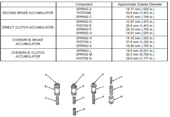
AW-4 ACCUMULATOR COMPONENT IDENTIFICATION
AW-4 TORQUE SPECIFICATIONS Description Torque Converter Housing Bolts . . . . . . . . . . . . . . . . . . . . .
fittings) . . . . . . . . . 18-23 N·m (160-200 in. lbs.) Description Torque Oil Pan Bolts . . . . . . . . . . . 6-8 N·m (53-70 in. lbs.) Description Torque Solenoid Harness Bolt . . . . 6-8 N·m (57-75 in. lbs.)Cleaning and inspection
Adjustments
Gearshift cable
Fig. 300 Shift Cable Attachment At Transmission-Typical
2 - TRANSMISSION SHIFT LEVER
3 - SHIFT CABLE
4 - SHIFT CABLE BRABrake transmission shift interlock
cable adjustment
Fig. 301 Park Lock Cable Attac
2 - CABLE LOCK BUTTON
3 - SHIFT LEVER ASSEMBLY
4 - SHIFT CABLETransmission throttle valve cable
adjustment
Fig. 302 Throttle Cable Components
2 - RELEASE BUTTON
3 - CABLE CONNECTOR
4 - CABLE
Fig. 303 Throttle Cable Adjustment
2 - ROTATE THROTTLE BODY LEVER TO W. O. T. POSITION
3 - CABLE
4 - CABLE BRACKETSpecifications
Second . . . . . . . . . . . . . . . . . . . . . . . . . . . 1.531:1
Third . . . . . . . . . . . . . . . . . . . . . . . . . . . . 1.000:1
Fourth (Overdrive) . . . . . . . . . . . . . . . . . . 0.753:1
Reverse . . . . . . . . . . . . . . . . . . . . . . . . . . 2.393:1
Fluid Level . To "Full" mark with fluid hot (normal
operating temperature)
Fluid Capacity (all models) . . . 8.0 Liters (8.45 qts.)
Line Pressure . . . . . . . . . . . . . . . . . . . . . . . . . . . . .
In D at Curb Idle . . . . . 61-70 psi (421-481 kPa)
In D at WOT . . . . . . 173-209 psi (1196-1442 kPa)
In Reverse at Curb Idle . 75-90 psi (519-618 kPa)
In Reverse at WOT . 213-263 psi (1471-1814 kPa)
Engagement in Reverse . . . . . . . . . . . 1.5 seconds
Valve Body Solenoid Resistance . . . . . . 11-15 ohms
TPS Input Voltage (AU) . . . . . . . 5.0 Volts (approx.)
TPS Output Voltage . . . . . . . . . . . . . . . . . . . . . . . . .
4-Cylinder . . . . . . . . . . . . . . . 0.2 Volts (approx.)
6-Cylinder . . . . . . . . . . . . . . . 4.2 Volts (approx.)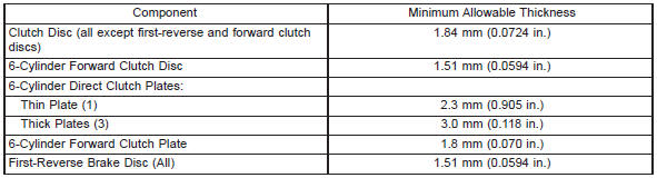
Standard . . . 0.11-0.14 mm (0.0043 -0.0055 in.)
Maximum Allowance . . . . . . . . 0.3 mm (0.012 in.)
Maximum Allowance . . . . . . . . 0.1 mm (0.004 in.)
Maximum Allowance . . . . . . . . 0.3 mm (0.012 in.)
10 mm . . . . . . . . . . . . 32-36 N·m (23-27 ft. lbs.)
12 mm . . . . . . . . . . . . 55-59 N·m (40-43 ft. lbs.)
Cooler Line Retaining Clip Nuts . . . . . . . . 2-4 N·m
(18-35 in. lbs.)
Cooler Line Bracket Nuts . . . . . . . . . . . . 5-11 N·m
(48-96 in. lbs.)
Cooler Line Fitting Nuts (at auto. trans.
Detent Spring Bolt . . . . . 9-11 N·m (80-96 in. lbs.)
Dust Cover Nuts/Bolts . . . . . . . . . . . . . . 18-23 N·m
(159-203 in. lbs.)
Extension Housing Bolts . . . . . . . . . . . . 32-36 N·m
(23-27 ft. lbs.)
Fill Tube Bracket Bolt . . 50-64 N·m (37-47 ft. lbs.)
Neutral Switch Bolt . . . . . 12-14 N·m (8-10 ft. lbs.)
Nut . . . . . . . . . . . . . . . . . 6-8 N·m (53-70 ft. lbs.)
OD Support Bolt (to case) . . . . . . . . . . . 23-27 N·m
(18-20 ft. lbs.)
Oil Pan Drain Plug . . . . 19-21 N·m (14-16 ft. lbs.)
Oil Pump Bolt (to case) . 21-23 N·m (16-18 ft. lbs.)
Oil Pump Bolt (to stator shaft) . . . . . . . . . 9-11N·m
(80-96 in. lbs.)
Oil Screen Bolt . . . . . . . . 9-11 N·m (80-96 in. lbs.)
Park Pawl Bracket . . . . . 9-11 N·m (80-96 in. lbs.)
Propeller Shaft Clamp Screws . . . . . . . . 16-23N·m
(140-200 in. lbs.)
Rear Mount-To-Transmission Bolts . . . . . 60-81N·m
(44 ft. lbs.)
Rear Mount-To-Clevis Bracket
Bolt/Nut . . . . . . . . . . . 54-75 N·m (40-55 ft. lbs.)
Rear Mount Clevis Bracket-To-Crossmember
Nuts . . . . . . . . . . . . . . 33-49 N·m (24-36 ft. lbs.)
Shift Cable Bracket Screws At
Transmission . . . . . 25-39 N·m (221-345 in. lbs.)
Shift Lever Mounting Cover Screws . . . . . 1-2 N·m
(9-20 in. lbs.)
Shift Lever Housing Nuts . . . . . . . . . . . 16-26 N·m
(141-230 in. lbs.)
Speedometer Adapter Clamp Screw . . . . 10-12 N·m
(90-110 in. lbs.)
Speed Sensor Coupling Nut . . . . . . . . . . 14-20 N·m
(125-175 in. lbs.)
Throttle Cable Engine Bracket Screws . . 7-11 N·m
(63-94 in. lbs.)
Throttle Cable Retaining Screw
(at transmission) . . . . . 8-10 N·m (70-98 in. lbs.)
Transfer Case Mounting Nuts . . . . . . . . 30-41 N·m
(22-30 ft. lbs.)
Transmission Shift Lever Nut . . . . . . . . 15-17 N·m
(134-154 in. lbs.)
Transmission-To-Engine Block Bolts . . . 50-64 N·m
(37-47 ft. lbs.)
Valve Body Bolts (to case) . . . . . . . . . . . . 9-11 N·m
(80-96 in. lbs.)
Valve Body Bolts (to valve body) . . . . . . . . 6-7 N·m
(54-58 in. lbs.)


Other materials:
Advanced Front Air Bag Operation. Occupant Classification System (OCS) - Front Passenger Seat. Occupant Classification Module (OCM) and Sensor
Advanced Front Air Bag Operation
Advanced Front Air Bags are designed to provide additional
protection by supplementing the seat belts. Advanced
Front Air Bags are not expected to reduce the risk
of injury in rear, side, or rollover collisions. The Advanced
Front Air Bags will not deploy in all ...