Jeep Cherokee (XJ): Cleaning and inspection. Adjustments. Specifications
Wash differential components with cleaning solvent
and dry with compressed air. Do not steam clean
the differential components.
Wash bearings with solvent and towel dry, or dry
with compressed air. DO NOT spin bearings with
compressed air. Cup and bearing must be
replaced as matched sets only.
Clean axle shaft tubes and oil channels in housing.
Inspect for; Clean all components in cleaning solvent. Dry components
with compressed air. Inspect clutch pack
plates for wear, scoring or damage. Replace both
clutch packs if any one component in either pack is
damaged. Inspect side gears and pinions. Replace
any gear that is worn, cracked, chipped or damaged.
Inspect differential case and pinion shaft. Replace if
worn or damaged. PRESOAK PLATES AND DISC Plates and discs with fiber coating (no grooves or
lines) must be presoaked in Friction Modifier before
assembly. Soak plates and discs for a minimum of 20
minutes. GENERAL INFORMATION Ring and pinion gears are supplied as matched
sets only. The identifying numbers for the ring and
pinion gear are etched into the face of each gear (Fig.
64). A plus (+) number, minus (-) number or zero (0)
is etched into the face of the pinion gear. This number
is the amount (in thousandths of an inch) the
depth varies from the standard depth setting of a
pinion etched with a (0). The standard setting from
the center line of the ring gear to the back face of the
pinion is 96.850 mm (3.813 in.). The standard depth
provides the best teeth contact pattern. Refer to
Backlash and Contact Pattern Analysis Paragraph in
this section for additional information.
1 - PRODUCTION NUMBERS Compensation for pinion depth variance is
achieved with select shims. The shims are placed
under the inner pinion bearing cone (Fig. 65).
If a new gear set is being installed, note the depth
variance etched into both the original and replacement
pinion gear. Add or subtract the thickness of
the original depth shims to compensate for the difference
in the depth variances. Refer to the Depth Variance
charts.
Note where Old and New Pinion Marking columns
intersect. Intersecting figure represents plus or
minus amount needed.
Note the etched number on the face of the drive
pinion gear (-1, -2, 0, +1, +2, etc.). The numbers represent
thousands of an inch deviation from the standard.
If the number is negative, add that value to the
required thickness of the depth shim(s). If the number
is positive, subtract that value from the thickness
of the depth shim(s). If the number is 0 no change is
necessary. Refer to the Pinion Gear Depth Variance
Chart.
1 - PINION GEAR DEPTH SHIM PINION GEAR DEPTH VARIANCE
PINION DEPTH MEASUREMENT AND ADJUSTMENT Measurements are taken with pinion cups and pinion
bearings installed in housing. Take measurements
with a Pinion Gauge Set, Pinion Block 6735,
Arbor Discs 6732, and Dial Indicator C-3339 (Fig.
66).
(1) Assemble Pinion Height Block 6739, Pinion
Block 6735, and rear pinion bearing onto Screw 6741
(Fig. 66).
(2) Insert assembled height gauge components,
rear bearing and screw into axle housing through
pinion bearing cups (Fig. 67).
(3) Install front pinion bearing and Cone 6740
hand tight (Fig. 66).
(4) Place Arbor Disc 6732 on Arbor D-115-3 in position
in axle housing side bearing cradles (Fig. 68).
Install differential bearing caps on Arbor Discs and
tighten cap bolts. Refer to the Torque Specifications
in this section.
NOTE: Arbor Discs 6732 have different step diameters
to fit other axle sizes. Pick correct size step for
axle being serviced.
(5) Assemble Dial Indicator C-3339 into Scooter
Block D-115-2 and secure set screw.
1 - DIAL INDICATOR
1 - PINION BLOCK 1 - ARBOR DISC (6) Place Scooter Block/Dial Indicator in position
in axle housing so dial probe and scooter block are
flush against the surface of the pinion height block.
Hold scooter block in place and zero the dial indicator
face to the pointer. Tighten dial indicator face
lock screw.
(7) With scooter block still in position against the
pinion height block, slowly slide the dial indicator
probe over the edge of the pinion height block.
Observe how many revolutions counterclockwise the
dial pointer travels (approximately 0.125 in.) to the
out-stop of the dial indicator.
(8) Slide the dial indicator probe across the gap
between the pinion height block and the arbor bar
with the scooter block against the pinion height block
(Fig. 69). When the dial probe contacts the arbor bar,
the dial pointer will turn clockwise. Bring dial
pointer back to zero against the arbor bar, do not
turn dial face. Continue moving the dial probe to the
crest of the arbor bar and record the highest reading.
If the dial indicator can not achieve the zero reading,
the rear bearing cup or the pinion depth gauge set is
not installed correctly.
(9) Select a shim equal to the dial indicator reading
plus the drive pinion gear depth variance number
etched in the face of the pinion gear (Fig. 64) using
the opposite sign on the variance number. For example,
if the depth variance is -2, add +0.002 in. to the
dial indicator reading.
(10) Remove the pinion depth gauge components
from the axle housing
1 - ARBOR Differential side bearing preload and gear backlash
is achieved by selective shims inserted between the
bearing cup and the axle housing. The proper shim
thickness can be determined using slip-fit dummy
bearings D-348 in place of the differential side bearings
and a dial indicator C-3339. Before proceeding
with the differential bearing preload and gear backlash
measurements, measure the pinion gear depth
and prepare the pinion gear for installation. Establishing
proper pinion gear depth is essential to establishing
gear backlash and tooth contact patterns.
After the overall shim thickness to take up differential
side play is measured, the pinion gear is
installed, and the gear backlash shim thickness is
measured. The overall shim thickness is the total of
the dial indicator reading, starting point shim thickness,
and the preload specification added together.
The gear backlash measurement determines the
thickness of the shim used on the ring gear side of
the differential case. Subtract the gear backlash shim
thickness from the total overall shim thickness and
select that amount for the pinion gear side of the differential
(Fig. 70). SHIM SELECTION NOTE: It is difficult to salvage the differential side
bearings during the removal procedure. Install
replacement bearings if necessary.
(1) Remove side bearings from differential case.
(2) Install ring gear, if necessary, on differential
case and tighten bolts to specification.
1 - PINION GEAR DEPTH SHIM (3) Install dummy side bearings D-348 on differential
case.
(4) Install differential case in axle housing.
(5) Insert Dummy Shims 8107 (0.118 in. (3.0 mm))
starting point shims between the dummy bearing
and the axle housing (Fig. 71).
1 - SPECIAL TOOL 8107 (6) Install the marked bearing caps in their correct
positions. Install and snug the bolts.
(7) Using a dead-blow type mallet, seat the differential
dummy bearings to each side of the axle housing
(Fig. 72) and (Fig. 73).
1 - MALLET
1 - AXLE HOUSING (8) Thread guide stud C-3288-B into rear cover
bolt hole below ring gear (Fig. 74).
(9) Attach dial indicator C-3339 to guide stud.
Position the dial indicator plunger on a flat surface
on a ring gear bolt head (Fig. 74).
(10) Push firmly and hold differential case to pinion
gear side of axle housing (Fig. 75).
(11) Zero dial indicator face to pointer.
1 - DIFFERENTIAL CASE (12) Push firmly and hold differential case to ring
gear side of the axle housing (Fig. 76).
(13) Record dial indicator reading.
1 - FORCE DIFFERENTIAL CASE TO PINION GEAR SIDE
1 - READ DIAL INDICATOR (14) Add the dial indicator reading to the starting
point shim thickness to determine total shim thickness
to achieve zero differential end play.
(15) Add 0.008 in. (0.2 mm) to the zero end play
total. This new total represents the thickness of
shims to compress, or preload the new bearings when
the differential is installed.
(16) Rotate dial indicator out of the way on guide
stud.
(17) Remove differential case, dummy bearings,
and starting point shims from axle housing.
(18) Install pinion gear in axle housing. Install the
yoke and establish the correct pinion rotating torque.
(19) Install differential case and dummy bearings
in axle housing (without shims) and tighten retaining
cap bolts.
(20) Position the dial indicator plunger on a flat
surface between the ring gear bolt heads (Fig. 74).
(21) Push and hold differential case toward pinion
gear.
(22) Zero dial indicator face to pointer.
(23) Push and hold differential case to ring gear
side of the axle housing.
(24) Record dial indicator reading.
(25) Subtract 0.002 in. (0.05 mm) from the dial
indicator reading to compensate for backlash between
ring and pinion gears. This total is the thickness of
shim required to achieve proper backlash.
(26) Subtract the backlash shim thickness from
the total preload shim thickness. The remainder is
the shim thickness required on the pinion side of the
axle housing.
(27) Rotate dial indicator out of the way on guide
stud.
(28) Remove differential case and dummy bearings
from axle housing.
(29) Install new side bearing cones and cups on
differential case.
(30) Install spreader W-129-B, utilizing some components
of Adapter Set 6987, on axle housing and
spread axle opening enough to receive differential
case.
(31) Place side bearing shims in axle housing
against axle tubes.
(32) Install differential case in axle housing.
(33) Rotate the differential case several times to
seat the side bearings.
(34) Position the indicator plunger against a ring
gear tooth (Fig. 77).
(35) Push and hold ring gear upward while not
allowing the pinion gear to rotate.
(36) Zero dial indicator face to pointer.
(37) Push and hold ring gear downward while not
allowing the pinion gear to rotate. Dial indicator
reading should be between 0.12 mm (0.005 in.) and
0.20 mm (0.008 in.). If backlash is not within specifications
transfer the necessary amount of shim thickness
from one side of the differential housing to the
other (Fig. 78). (38) Verify differential case and ring gear runout
by measuring ring to pinion gear backlash at eight
locations around the ring gear. Readings should not
vary more than 0.05 mm (0.002 in.). If readings vary
more than specified, the ring gear or the differential
case is defective.
After the proper backlash is achieved, perform the
Gear Contact Pattern Analysis procedure.
1 - DIAL INDICATOR The ring gear and pinion teeth contact patterns
will show if the pinion depth is correct in the axle
housing. It will also show if the ring gear backlash
has been adjusted correctly. The backlash can be
adjusted within specifications to achieve desired
tooth contact patterns.
(1) Apply a thin coat of hydrated ferric oxide, or
equivalent, to the drive and coast side of the ring
gear teeth.
(2) Wrap, twist, and hold a shop towel around the
pinion yoke to increase the turning resistance of the
pinion. This will provide a more distinct contact pattern.
(3) Using a boxed end wrench on a ring gear bolt,
Rotate the differential case one complete revolution
in both directions while a load is being applied from
shop towel.
The areas on the ring gear teeth with the greatest
degree of contact against the pinion teeth will squeegee
the compound to the areas with the least amount
of contact. Note and compare patterns on the ring
gear teeth to Gear Tooth Contact Patterns chart (Fig.
79) and adjust pinion depth and gear backlash as
necessary.
DESCRIPTION SPECIFICATION Axle Type . . . . . . . . . . . . . . . Semi-Floating Hypoid DESCRIPTION TORQUE Bolt, Diff. Cover . . . . . . . . . . . . 41 N·m (30 ft. lbs.)Cleaning and inspection
Axle components
Trac-lok
Adjustments
Pinion gear depth
Fig. 64 Pinion Gear ID Numbers
2 - DRIVE PINION GEAR DEPTH VARIANCE
3 - GEAR MATCHING NUMBER (SAME AS RING GEAR
NUMBER)
Fig. 65 Shim Locations
2 - DIFFERENTIAL BEARING SHIM-PINION GEAR SIDE
3 - RING GEAR
4 - DIFFERENTIAL BEARING SHIM-RING GEAR SIDE
5 - COLLAPSIBLE SPACER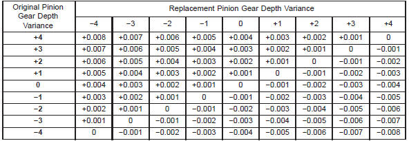
Fig. 66 Pinion Gear Depth Gauge Tools-Typical
2 - ARBOR
3 - PINION HEIGHT BLOCK
4 - CONE
5 - SCREW
6 - PINION BLOCK
7 - SCOOTER BLOCK
8 - ARBOR DISC
Fig. 67 Pinion Height Block-Typical
2 - PINION HEIGHT BLOCK
2 - PINION BLOCK
3 - ARBOR
4 - PINION HEIGHT BLOCK
Fig. 69 Pinion Gear Depth Measurement-Typical
2 - SCOOTER BLOCK
3 - DIAL INDICATORDifferential bearing preload and
gear backlash
Fig. 70 Axle Adjustment Shim Locations
2 - DIFFERENTIAL BEARING SHIM-PINION GEAR SIDE
3 - RING GEAR
4 - DIFFERENTIAL BEARING SHIM-RING GEAR SIDE
5 - COLLAPSIBLE SPACER
Fig. 71 Insert Starting Point Shims
2 - AXLE HOUSING
3 - DIFFERENTIAL CASE
4 - SPECIAL TOOL D-348
Fig. 72 Seat Pinion Gear Dummy Side Bearing
2 - AXLE HOUSING
3 - DIFFERENTIAL CASE
Fig. 73 Seat Ring Gear Side Dummy Bearing
2 - MALLET
3 - DIFFERENTIAL CASE
Fig. 74 Differential Side play Measurement
2 - AXLE HOUSING
3 - SPECIAL TOOL C-3288-B
4 - SPECIAL TOOL C-3339
Fig. 75 Hold Differential Case and Zero Dial
Indicator
2 - SPECIAL TOOL C-3288-B
3 - SPECIAL TOOL C-3339
4 - ZERO DIAL INDICATOR FACE
Fig. 76 Hold Differential Case and Read Dial Indicator
2 - FORCE DIFFERENTIAL CASE TO RING GEAR SIDE
3 - AXLE HOUSING
Fig. 77 Ring Gear Backlash MeasurementGear contact pattern analysis
Fig. 78 Backlash Shim Adjustment
Fig. 79 Gear Tooth Contact PatternsSpecifications
194 RBI axle
Lubricant . . . . . . . . SAE Thermally Stable 80W-90
Lubricant Trailer Tow . . . . . . . Synthetic 75W-140
Lube Capacity . . . . . . . . . . . . . . . 1.66 L (3.50 pts.)
Friction Modifier . . . . . . . . . . . . . 0.12 L (3.50 ozs.)
Axle Ratios . . . . . . . . . . . . . . . . . . . 3.07, 3.55, 3.73
Differential Bearing Preload . . . 0.1 mm (0.008 in.)
Differential Side Gear Clearance . . . . . . 0-0.15 mm
(0-0.006 in.)
Ring Gear Diameter . . . . . . . . . 19.2 cm (7.562 in.)
Ring Gear Backlash . . 0-0.15 mm (0.005-0.008 in.)
Pinion Std. Depth . . . . . . . . . . 96.85 mm (3.813 in.)
Pinion Bearing Preload-Original Bearings . . . . . . . . . . . . 1-2 N·m (10-20
in. lbs.)
Pinion Bearing Preload-New Bearings . . 1.5-4 N·m
(15-35 in. lbs.)194 RBI axle
Bolt, Bearing Cap . . . . . . . . . . . 77 N·m (57 ft. lbs.)
Nut, Pinion . . . . . . . 271-474 N·m (200-350 ft. lbs.)
Screw, Pinion Mate Shaft Lock . . . . . . . . 16.25 N·m
(12 ft. lbs.)
Bolt, Ring Gear . . . . . . 95-122 N·m (70-90 ft. lbs.)
Bolt, RWAL/ABS Sensor . . . . . . . 8 N·m (70 in. lbs.)


Other materials:
Removal and installation
Radio
WARNING: ON VEHICLES EQUIPPED WITH AIRBAGS,
REFER TO GROUP 8M - PASSIVE
RESTRAINT SYSTEMS BEFORE ATTEMPTING ANY
STEERING WHEEL, STEERING COLUMN, OR
INSTRUMENT PANEL COMPONENT DIAGNOSIS OR
SERVICE. FAILURE TO TAKE THE PROPER PRECAUTIONS
COULD RESULT IN ACCIDENTAL AIRBAG
DEPLOYMENT AND PO ...