Jeep Cherokee (XJ): Cleaning and inspection. Adjustments. Specifications
Wash differential components with cleaning solvent
and dry with dry compressed air. Do not steam
clean the differential components.
Wash bearings with solvent and towel dry, or dry
with compressed air. DO NOT spin bearings with
compressed air. Cup and bearing must be
replaced as matched sets only.
Be sure that the axle tubes and oil channels are
thoroughly cleaned in the housing.
Inspect for: Polish each axle shaft sealing surface with No. 600
crocus cloth. This can remove slight surface damage.
Do not reduce the diameter of the axle shaft seal contact
surface. When polishing, the crocus cloth should
be moved around the circumference of the shaft (not
in-line with the shaft). Clean all components in cleaning solvent. Dry components
with compressed air. Inspect clutch pack
plates for wear, scoring or damage. Replace both
clutch packs if any one component in either pack is
damaged. Inspect side gears and pinions. Replace
any gear that is worn, cracked, chipped or damaged.
Inspect differential case and pinion shaft. Replace if
worn or damaged. PRESOAK PLATES AND DISC Plates and discs with fiber coating (no grooves or
lines) must be presoaked in Friction Modifier before
assembly. Soak plates and discs for a minimum of 20
minutes. GENERAL INFORMATION Ring gears and pinions are supplied as matched
sets only. The identifying numbers for the ring gear
and pinion are etched into the face of each gear (Fig.
51). A plus (+) number, minus (-) number or zero (0)
is etched into the face of the pinion. This number is
the amount (in thousandths of an inch) the depth
varies from the standard depth setting of a pinion
etched with a (0). The standard depth provides the
best gear tooth contact pattern. Refer to Backlash
and Contact Pattern Analysis paragraph in this section
for additional information.
1 - PRODUCTION NUMBERS Compensation for pinion depth variance is
achieved with select shims. The shims are placed
behind the rear pinion bearing (Fig. 52).
If a new gear set is being installed, note the depth
variance etched into both the original and replacement
pinion. Add or subtract the thickness of the
original depth shims to compensate for the difference
in the depth variances. Refer to the Depth Variance
chart.
Note where Old and New Pinion Marking columns
intersect. Intersecting figure represents plus or
minus the amount needed.
Note the etched number on the face of the pinion
gear head (-1, -2, 0, +1, +2, etc.). The numbers represent
thousands of an inch deviation from the standard.
If the number is negative, add that value to the
required thickness of the depth shims. If the number
is positive, subtract that value from the thickness of
the depth shim. If the number is 0 no change is necessary.
1 - AXLE HOUSING PINION DEPTH MEASUREMENT AND ADJUSTMENT Measurements are taken with pinion bearing cups
and pinion bearings installed in the axle housing.
Take measurements with Pinion Gauge Set and Dial
Indicator C-3339 (Fig. 53).
(1) Assemble Pinion Height Block 6739, Pinion
Block 8540, and rear pinion bearing onto Screw 6741
(Fig. 53).
(2) Insert assembled height gauge components,
rear bearing, and screw into axle housing through
pinion bearing cups (Fig. 54).
(3) Install front pinion bearing and Cone-Nut 6740
hand tight (Fig. 53).
(4) Place Arbor Disc 8541 on Arbor D-115-3 in position
in axle housing side bearing cradles (Fig. 55).
Install differential bearing caps on Arbor Discs and
tighten cap bolts to 41 N·m (30 ft. lbs.).
NOTE: Arbor Discs 8541 has different step diameters
to fit other axles. Choose proper step for axle
being serviced.
(5) Assemble Dial Indicator C-3339 into Scooter
Block D-115-2 and secure set screw.
(6) Place Scooter Block/Dial Indicator in position
in axle housing so dial probe and scooter block are
flush against the rearward surface of the pinion
height block (Fig. 53). Hold scooter block in place and
zero the dial indicator face to the pointer. Tighten
dial indicator face lock screw. PINION GEAR DEPTH VARIANCE
1 - DIAL INDICATOR (7) With scooter block still in position against the
pinion height block, slowly slide the dial indicator
probe over the edge of the pinion height block.
(8) Slide the dial indicator probe across the gap
between the pinion height block and the arbor bar
with the scooter block against the pinion height block
(Fig. 56). When the dial probe contacts the arbor bar,
the dial pointer will turn clockwise. Bring dial
pointer back to zero against the arbor bar, do not
turn dial face. Continue moving the dial probe to the
crest of the arbor bar and record the highest reading.
If the dial indicator can not achieve the zero reading,
the rear bearing cup or the pinion depth gauge set is
not installed correctly.
(9) Select a shim equal to the dial indicator reading
plus the drive pinion gear depth variance number
etched in the face of the pinion (Fig. 51). For example,
if the depth variance is -2, add +0.002 in. to the
dial indicator reading. The following must be considered when adjusting
bearing preload and gear backlash:
1 - ARBOR DISC
1 - ARBOR NOTE: The differential bearing cups will not always
immediately follow the threaded adjusters as they
are moved during adjustment. To ensure accurate
bearing cup responses to the adjustments: (1) Use Wrench C-4164 to adjust each threaded
adjuster inward until the differential bearing freeplay
is eliminated (Fig. 57). Allow some ring gear
backlash (approximately 0.01 inch/0.25 mm) between
the ring and pinion gear. Seat the bearing cups with
the procedure described above.
1 - AXLE TUBE (2) Install dial indicator and position the plunger
against the drive side of a ring gear tooth (Fig. 58).
Measure the backlash at 4 positions (90 degrees
apart) around the ring gear. Locate and mark the
area of minimum backlash.
(3) Rotate the ring gear to the position of the least
backlash. Mark the gear so that all future backlash
measurements will be taken with the same gear
teeth meshed.
(4) Loosen the right-side, tighten the left-side
threaded adjuster. Obtain backlash of 0.003 to 0.004
inch (0.076 to 0.102 mm) with each adjuster tightened
to 14 N·m (10 ft. lbs.). Seat the bearing cups
with the procedure described above.
(5) Tighten the differential bearing cap bolts 95
N·m (70 ft. lbs.).
(6) Tighten the right-side threaded adjuster to 102
N·m (75 ft. lbs.). Seat the bearing cups with the procedure described above.
Continue to tighten the
right-side adjuster and seat bearing cups until the
torque remains constant at 102 N·m (75 ft. lbs.)
(7) Measure the ring gear backlash. The range of
backlash is 0.006 to 0.008 inch (0.15 to 0.203 mm).
(8) Continue increasing the torque at the rightside
threaded adjuster until the specified backlash is
obtained.
1 - DIAL INDICATOR (7) Measure the ring gear backlash. The range of
backlash is 0.006 to 0.008 inch (0.15 to 0.203 mm).
(8) Continue increasing the torque at the rightside
threaded adjuster until the specified backlash is
obtained.
NOTE: The left-side threaded adjuster torque
should have approximately 102 N·m (75 ft. lbs.). If
the torque is considerably less, the complete
adjustment procedure must be repeated.
(9) Tighten the left-side threaded adjuster until
102 N·m (75 ft. lbs.) torque is indicated. Seat the
bearing rollers with the procedure described above.
Do this until the torque remains constant.
(10) Install the threaded adjuster locks and
tighten the lock screws to 10 N·m (90 in. lbs.).
After the proper backlash is achieved, perform the
Gear Contact Analysis procedure. The ring gear and pinion teeth contact patterns
will show if the pinion depth is correct in the axle
housing. It will also show if the ring gear backlash
has been adjusted correctly. The backlash can be
adjusted within specifications to achieve desired
tooth contact patterns.
(1) Apply a thin coat of hydrated ferric oxide, or
equivalent, to the drive and coast side of the ring
gear teeth.
(2) Wrap, twist, and hold a shop towel around the
pinion yoke to increase the turning resistance of the
pinion. This will provide a more distinct contact pattern.
(3) Using a boxed end wrench on a ring gear bolt,
Rotate the differential case one complete revolution
in both directions while a load is being applied from
shop towel.
The areas on the ring gear teeth with the greatest
degree of contact against the pinion teeth will squeegee
the compound to the areas with the least amount
of contact. Note and compare patterns on the ring
gear teeth to Gear Tooth Contact Patterns chart (Fig.
59) and adjust pinion depth and gear backlash as
necessary. When measuring side gear clearance, check each
gear independently. If it necessary to replace a side
gear, replace both gears as a matched set.
(1) Install the axle shafts and C-locks and pinion
mate shaft.
(2) Measure each side gear clearance. Insert a
matched pair of feeler gauge blades between the gear
and differential housing on opposite sides of the hub
(Fig. 60).
(3) If side gear clearances is no more than 0.005
inch. Determine if the axle shaft is contacting the
pinion mate shaft. Do not remove the feeler
gauges, inspect the axle shaft with the feeler
gauge inserted behind the side gear. If the end of
the axle shaft is not contacting the pinion mate
shaft, the side gear clearance is acceptable.
(4) If clearance is more than 0.005 inch (axle shaft
not contacting mate shaft), record the side gear clearance.
Remove the thrust washer and measure its
thickness with a micrometer. Add the washer thickness
to the recorded side gear clearance. The sum of
gear clearance and washer thickness will determine
required thickness of replacement thrust washer
(Fig. 61).
In some cases, the end of the axle shaft will move
and contact the mate shaft when the feeler gauge is
inserted. The C-lock is preventing the side gear from
sliding on the axle shaft.
(5) If there is no side gear clearance, remove the
C-lock from the axle shaft. Use a micrometer to measure
the thrust washer thickness. Record the thickness
and re-install the thrust washer. Assemble the
differential case without the C-lock installed and remeasure
the side gear clearance.
(6) Compare both clearance measurements. If the
difference is less than 0.012 inch (0.305 mm), add
clearance recorded when the C-lock was installed to
thrust washer thickness measured. The sum will
determine the required thickness of the replacement
thrust washer.
1 - FEELER GAUGE BLADES
(7) If clearance is 0.012 inch (0.305 mm) or
greater, both side gears must be replaced (matched
set) and the clearance measurements repeated.
(8) If clearance (above) continues to be 0.012 inch
(0.305 mm) or greater, the case must be replaced. Axle Type . . . . . . . . . . . . . . . Semi-floating, hypoid Differential Case Clearance . . . . . . . . . . . . . 0.12 mm (0.005 in.) Ring Gear Diameter . . . . . . . . . . . . . . . . . . 20.95 cm (8.25 in.) Pinion Bearing Preload-Used Bearings . . . . 1-2 N·m (10-20 in.lbs.) DESCRIPTION TORQUE Diff. Cover Bolt . . . . . . . . . . . . . 41 N·m (30 ft. lbs.)Cleaning and inspection
8 1/4 Axle
Trac-lok
Adjustments
1/4 Axle pinion gear depth
Fig. 51 Pinion Gear ID Numbers
2 - DRIVE PINION GEAR DEPTH VARIANCE
3 - GEAR MATCHING NUMBER (SAME AS RING GEAR
NUMBER)
Fig. 52 Shim Locations
2 - COLLAPSIBLE SPACER
3 - PINION BEARING
4 - PINION DEPTH SHIM
5 - PINION GEAR
6 - BEARING CUP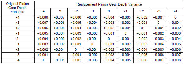
Fig. 53 Pinion Gear Depth Gauge Tools-Typical
2 - ARBOR
3 - PINION HEIGHT BLOCK
4 - CONE
5 - SCREW
6 - PINION BLOCK
7 - SCOOTER BLOCK
8 - ARBOR DISC
Fig. 54 Pinion Height Block-TypicalDifferential bearing preload and
gear backlash
Fig. 55 Gauge Tools In Housing-Typical
2 - PINION BLOCK
3 - ARBOR
4 - PINION HEIGHT BLOCK
Fig. 56 Pinion Gear Depth Measurement-Typical
2 - SCOOTER BLOCK
3 - DIAL INDICATOR
Fig. 57 Threaded Adjuster Tool
2 - BACKING PLATE
3 - TOOL C-4164
Fig. 58 Ring Gear Backlash Measurement
2 - RING GEAR
3 - EXCITER RINGGear contact pattern analysis
Side gear clearance
Fig. 59 Gear Tooth Contact Patterns
Fig. 60 Side Gear Clearance Measurement
2 - SIDE GEAR
Fig. 61 Side Gear CalculationsSpecifications
8 1/4 Inch axle
Lubricant . . . . . . . . . . . . . . . . . . . . . . SAE 80W-90
Lube Capacity . . . . . . . . . . . . . . . . 2.08 L (4.4 pts.)
Trac-Lok Additive . . . . . . . . . . . . . . . 118 ml (4 oz.)
Axle Ratio . . . . . . . . . . . . . . . . . . . . 3.07, 3.55,.4.10
Case Flange Runout . . . . . . . . 0.076 mm (0.003 in.)
Backlash . . . . . . . . . 0.12-0.20 mm (0.005-0.008 in.)
Runout . . . . . . . . . . . . . . . . . . 0.127 mm (0.005 in.)
Preload-New Bearings . . . . . 1-5 N·m (10-30 in.lbs.)8 1/4 Inch axle
Bearing Cap Bolt . . . . . . . . . . 136 N·m (100 ft. lbs.)
Pinion Nut-Minimum . . . . . . 285 N·m (210 ft. lbs.)
Ring Gear Bolt . . . . . . . . . . . . . 95 N·m (70 ft. lbs.)
Backing Plate Bolt . . . . . . . . . 614 N·m (45 ft. lbs.)
RWAL/ABS Sensor Bolt . . . . . . 24 N·m (18. ft. lbs.)
 Service procedures. Removal and installation. Disassembly and assembly

Other materials:
Lamp bulb service
REMOVAL AND INSTALLATIONHeadlamp bulb
REMOVAL
(1) Remove the screws attaching the bezel to the
grille opening panel (Fig. 1).
(2) Remove screws attaching the retaining ring to
the headlamp canister.
(3) Disconnect the headlamp bulb wire harness
connector.
(4) Separate the sealed beam fr ...