Jeep Cherokee (XJ): Crankshaft main bearings
REMOVAL
(1) Disconnect negative cable from battery.
(2) Remove the spark plugs.
(3) Raise the vehicle.
(4) Remove the oil pan and oil pump.
(5) Remove main bearing cap brace (Fig. 67).
(6) Remove only one main bearing cap and lower insert at a time (Fig. 68).
(7) Remove the lower insert from the bearing cap.
(8) Remove the upper insert by LOOSENING (DO NOT REMOVE) all of the other bearing caps. Now insert a small cotter pin tool in the crankshaft journal oil hole. Bend the cotter pin as illustrated to fabricate the tool (Fig. 69). With the cotter pin tool in place, rotate the crankshaft so that the upper bearing insert will rotate in the direction of its locking tab. Because there is no hole in the No.3 main journal, use a tongue depressor or similar soft-faced tool to remove the bearing insert (Fig. 69). After moving the insert approximately 25 mm (1 inch), it can be removed by applying pressure under the tab.
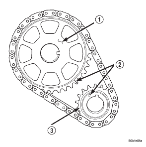
Fig. 66 Crankshaft / Camshaft Chain Drive Installation-Typical
1 - CAMSHAFT SPROCKET
2 - TIMING MARKS
3 - CRANKSHAFT SPROCKET
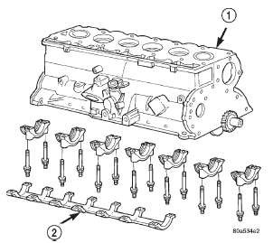
Fig. 67 Main Bearing Caps and Brace.
1 - BLOCK
2 - MAIN BEARING CAP BRACE
(9) Using the same procedure described above, remove the remaining bearing inserts one at a time for inspection.
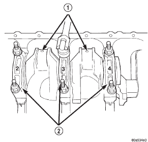
Fig. 68 Removing Main Bearing Caps and Lower Inserts
1 - CONNECTING ROD JOURNAL
2 - MAIN BEARING CAPS
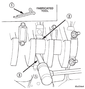
Fig. 69 Removing Upper Inserts
1 - COTTER PIN
2 - BEARING INSERT
3 - TONGUE DEPRESSOR
INSTALLATION
(1) Lubricate the bearing surface of each insert with engine oil.
(2) Loosen all the main bearing caps. Install the main bearing upper inserts.
(3) Install the lower bearing inserts into the main bearing caps.
(4) On the rear main cap, apply Mopart Gasket Maker sealer on both sides of cylinder block as shown in (Fig. 70). The dab of sealer should be 3 mm (0.125 in.) in diameter.
(5) Apply Mopart Gasket Maker on the rear bearing cap. The bead should be 2.3 mm (0.09 in.) in diameter. DO NOT apply sealer to the lip of the seal.
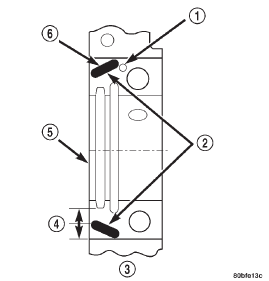
Fig. 70 Location of Sealer
1 - DOWEL
2 - SEALER LOCATIONS
3 - CYLINDER BLOCK
4 - HALFWAY BETWEEN
5 - REAR FACE OF CYLINDER BLOCK
6 - 3mm (0.125 in.)
(6) Install the main bearing cap(s) and lower insert(s).
(7) Tighten the bolts of caps 1, 2, 4, 5, 6, and 7 to 54 N·m (40 ft. lbs.) torque. Now tighten these bolts to 95 N·m (70 ft. lbs.) torque. Finally, tighten these bolts to 108 N·m (80 ft. lbs.) torque.
(8) Push the crankshaft forward and backward.
Load the crankshaft front or rear and tighten cap bolt No.3 to 54 N·m (40 ft. lbs.) torque. Then tighten to 95 N·m (70 ft. lbs.) torque and finally tighten to 108 N·m (80 ft. lbs.) torque.
(9) Rotate the crankshaft after tightening each main bearing cap to ensure the crankshaft rotates freely.
(10) Check crankshaft end play. Crankshaft end play is controlled by the thrust bearing which is flange and installed at the No.2 main bearing position.
(a) Attach a magnetic base dial indicator to the cylinder block at either the front or rear of the engine.
(b) Position the dial indicator rod so that it is parallel to the center line of the crankshaft.
(c) Pry the crankshaft forward, position the dial indicator to zero.
(d) Pry the crankshaft forward and backward.
Note the dial indicator readings. End play is the difference between the high and low measurements (Fig. 71). Correct end play is 0.038-0.165 mm (0.0015-0.0065 inch). The desired specifications are 0.051-0.064 mm (0.002-0.0025 inch).
(e) If end play is not within specification, inspect crankshaft thrust faces for wear. If no wear is apparent, replace the thrust bearing and measure end play. If end play is still not within specification, replace the crankshaft.
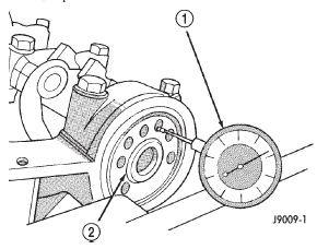
Fig. 71 Crankshaft End Play Measurement
1 - DIAL INDICATOR
2 - CRANKSHAFT
(11) If the crankshaft was removed, install the crankshaft into the cylinder block (refer to Cylinder Block - Assemble).
(12) Install main bearing cap brace tighten nuts to 47 N·m (35 ft. lbs.) torque.
(13) Install oil pump assy. and tighten attaching bolts to 23 N·m (17 ft. lbs.) (14) Install the oil pan.
(15) Install the drain plug. Tighten the plug to 34 N·m (25 ft. lbs.) torque.
(16) Lower the vehicle.
(17) Install the spark plugs. Tighten the plugs to 37 N·m (27 ft. lbs.) torque.
(18) Fill the oil pan with engine oil to the full mark on the dipstick level.
(19) Connect negative cable to battery.
 Timing chain and sprockets. Camshaft. Camshaft bearings

Other materials:
Schematics and diagrams. Specifications. Special tools
Schematics and diagrams
HYDRAULIC SCHEMATICS
Fig. 235 Throttle Pressure Adjustment
1 - HEX WRENCH (IN THROTTLE LEVER ADJUSTING SCREW)
2 - SPECIAL TOOL C-3763 (POSITIONED BETWEEN THROTTLE
LEVER AND KICKDOWN VALVE)
HYDRAULIC FLOW IN PARK/NEUTRAL
HYDRAULIC FLOW IN D-FIRST GEAR
HY ...