Jeep Cherokee (XJ): Description and operation. Diagnosis and testing. Removal and installation
DESCRIPTION The NV242 is a full-time transfer case (Fig. 1). It
provides full time 2-wheel, or 4-wheel drive operation.
A differential in the transfer case is used to control
torque transfer to the front and rear axles. A low
range gear provides increased low speed torque capability
for off road operation. The low range provides a
2.72:1 reduction ratio.
The input gear is splined to the transmission output
shaft. It drives the mainshaft through the planetary
gear and range hub. The front output shaft is
operated by a drive chain that connects the shaft to a
drive sprocket on the mainshaft. The drive sprocket
is engaged/disengaged by the mode fork, which operates
the mode sleeve and hub. The sleeve and hub
are not equipped with a synchro mechanism for shifting.
The geartrain is mounted in two aluminum case
halves attached with bolts. The mainshaft front and
rear bearings are mounted in aluminum retainer
housings bolted to the case halves. TRANSFER CASE IDENTIFICATION A circular ID tag is attached to the rear case of
each transfer case (Fig. 2). The ID tag provides the
transfer case model number, assembly number, serial
number, and low range ratio.
The transfer case serial number also represents
the date of build.
1 - I. D. TAG OPERATING RANGES NV242 operating ranges are 2WD (2-wheel drive),
4x4 part-time, 4x4 full time, and 4 Lo.
The 2WD and 4x4 full time ranges can be used at
any time and on any road surface.
The 4x4 part-time and 4 Lo ranges are for off road
use only. The only time these ranges can be used on
hard surface roads, is when the surface is covered
with snow and ice. SHIFT MECHANISM Operating ranges are selected with a floor mounted
shift lever. The shift lever is connected to the transfer
case range lever by an adjustable linkage rod. A
straight line shift pattern is used. Range positions
are marked on the shifter bezel cover plate, or on the
shift knob. DESCRIPTION Recommended lubricant for the NV242 transfer
case is Mopart Dexron II, or ATF Plus, type 7176.
Approximate lubricant fill capacity is 1.35 liters (2.85
pints).
The fill and drain plugs are both in the rear case
(Fig. 3). Correct fill level is to the bottom edge of the
fill plug hole. Be sure the vehicle is level to ensure
an accurate fluid level check.
1 - I. D. TAG NV242 DIAGNOSIS DIAGNOSIS CHART CONDITION POSSIBLE CAUSE CORRECTION REMOVAL (1) Shift transfer case into Neutral.
(2) Raise vehicle.
(3) Drain transfer case lubricant.
(4) Mark front and rear propeller shaft yokes for
alignment reference.
(5) Support transmission with jack stand.
(6) Remove rear crossmember, or skid plate.
(7) Disconnect front/rear propeller shafts at transfer
case.
(8) Disconnect vehicle speed sensor wires.
(9) Disconnect transfer case linkage rod from
range lever.
(10) Disconnect transfer case vent hose (Fig. 4)
and indicator switch harness, if necessary.
(11) Support transfer case with transmission jack.
(12) Secure transfer case to jack with chains.
(13) Remove nuts attaching transfer case to transmission.
(14) Pull transfer case and jack rearward to disengage
transfer case.
(15) Remove transfer case from under vehicle. INSTALLATION (1) Mount transfer case on a transmission jack.
(2) Secure transfer case to jack with chains.
(3) Position transfer case under vehicle.
(4) Align transfer case and transmission shafts
and install transfer case on transmission.
(5) Install and tighten transfer case attaching nuts
to 35 N·m (26 ft. lbs.) torque (Fig. 4).
(6) Connect vehicle speed sensor wires, and vent
hose.
(7) Connect indicator switch harness to transfer
case switch, if necessary. Secure wire harness to clips
on transfer case.
(8) Align and connect propeller shafts. Refer to
Group 3, Differential and Driveline, for proper procedures
and specifications. 1 - VENT TUBE (9) Fill transfer case with correct fluid. Check
transmission fluid level. Correct as necessary.
(10) Install rear crossmember, or skid plate.
Tighten crossmember bolts to 41 N·m (30 ft. lbs.)
torque.
(11) Remove transmission jack and support stand.
(12) Connect shift rod to transfer case range lever.
(13) Adjust transfer case shift linkage.
(14) Lower vehicle and verify transfer case shift
operation. REMOVAL (1) Shift transfer case into 4L.
(2) Raise vehicle.
(3) Loosen adjusting trunnion locknut and slide
shift rod out of trunnion (Fig. 5). If rod lacks enough
travel to come out of trunnion, push trunnion out of
torque shaft.
(4) Lower vehicle.
(5) Remove console. Refer to Group 23, Body, for
proper procedures. (6) Remove screws attaching lever assembly to
floorpan and remove assembly and shift rod (if left
attached). INSTALLATION (1) If shift rod was not removed from lever assembly,
work rod down through floorpan opening. Then
position lever assembly on floorpan and install
assembly attaching screws.
(2) Install console. Refer to Group 23, Body, for
proper procedures.
(3) Raise vehicle.
(4) Connect trunnion to torque shaft arm. Or, slide
shift rod into trunnion on range lever. Be sure shift
rod slides freely in trunnion.
(5) Verify that range lever is in 4L position. Then
tighten trunnion lock bolt.
(6) Lower vehicle and check transfer case shift
operation. REMOVAL (1) Raise vehicle.
(2) Disconnect wires from vehicle speed sensor.
(3) Remove adapter clamp and screw (Fig. 6).
(4) Remove speed sensor and speedometer adapter
as an assembly.
(5) Remove speed sensor retaining screw and
remove sensor from adapter.
(6) Remove speedometer pinion from adapter.
Replace pinion if chipped, cracked, or worn.
(7) Inspect sensor and adapter O-rings (Fig. 6).
Remove and discard O-rings if worn or damaged.
(8) Inspect terminal pins in speed sensor. Clean
pins with Mopart electrical spray cleaner if dirty or
oxidized. Replace sensor if faulty, or if pins are loose,
severely corroded, or damaged.
1 - RIVNUT (4)
1 - SENSOR O-RING INSTALLATION AND INDEXING (1) Thoroughly clean adapter flange and adapter
mounting surface in housing. Surfaces must be clean
for proper adapter alignment and speedometer operation.
(2) Install new O-rings on speed sensor and speedometer
adapter (Fig. 6), if necessary.
(3) Lubricate sensor and adapter O-rings with
transmission fluid.
(4) Install vehicle speed sensor in speedometer
adapter. Tighten sensor attaching screw to 2-3 N·m
(15-27 in. lbs.) torque.
(5) Install speedometer pinion in adapter.
(6) Count number of teeth on speedometer pinion.
Do this before installing assembly in housing. Then
lubricate pinion teeth with transmission fluid.
(7) Note index numbers on adapter body (Fig. 7).
These numbers will correspond to number of teeth on
pinion.
(8) Install speedometer assembly in housing.
(9) Rotate adapter until required range numbers
are at 6 o-clock position. Be sure range index numbers
correspond to number of teeth on pinion gear.
(10) Install speedometer adapter clamp and retaining
screw. Tighten clamp screw to 10-12 N·m (90-110
in. lbs.) torque.
(11) Connect wires to vehicle speed sensor.
(12) Lower vehicle and top off transmission fluid
level if necessary.
1 - SPEEDOMETER ADAPTER REMOVAL (1) Raise vehicle.
(2) Remove front propeller shaft. Refer to Group 3,
Differential and Driveline, for proper procedure. (3) Remove front output shaft yoke.
(4) Remove seal from front case with pry tool (Fig.
8).
1 - OUTPUT SHAFT SEAL INSTALLATION (1) Install new front output seal in front case with
Installer Tool 6952-A as follows:
(a) Place new seal on tool. Garter spring on seal
goes toward interior of case.
(b) Start seal in bore with light taps from hammer
(Fig. 9). Once seal is started, continue tapping
seal into bore until installer tool seats against case.
1 - INSTALLER 6952-ADescription and operation
NV242 transfer case
Fig. 1 NV242 Transfer Case
Fig. 2 Fill/Drain Plug And I. D. Tag Locations
2 - FILL PLUG
3 - DRAIN PLUGLubricant and fill level
Fig. 3 Fill/Drain Plug Locations
2 - FILL PLUG
3 - DRAIN PLUGDiagnosis and testing
Transfer case difficult to shift or will
not shift into desired range.
Transfer case noisy in all drive
modes.
Lubricant leaking from transfer case
seals or vent.
Transfer case will not shift through
4X4 part time range (light remains
on)
Removal and installation
Transfer case
2 - TRANSFER CASE
3 - TRANSMISSIONShift lever
Speedometer
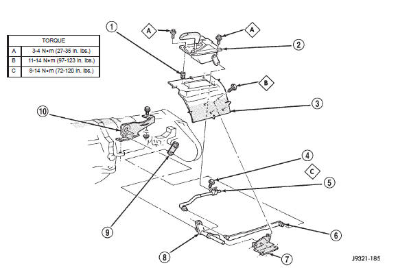
Fig. 5 Shift Linkage
2 - SHIFT LEVER ASSEMBLY
3 - FLOORPAN
4 - TRUNNION LOCK BOLT
5 - SELECTOR ROD AND TRUNNION
6 - SHIFT LEVER ROD
7 - TORQUE SHAFT FRAME BRACKET
8 - TORQUE SHAFT
9 - TRANSFER CASE SHIFT LEVER
10 - TORQUE SHAFT TRANSFER CASE BRACKET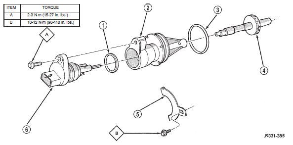
Fig. 6 Speedometer Components
2 - SPEEDOMETER ADAPTER
3 - ADAPTER O-RING
4 - SPEEDOMETER PINION
5 - ADAPTER CLAMP
6 - VEHICLE SPEED SENSOR
Fig. 7 Location Of Index Numbers On Speedometer Adapter
2 - INDEX NUMBER LOCATIONFront output shaft seal
Fig. 8 Remove Front Output Shaft Seal
2 - PRYBAR
Fig. 9 Front Output Seal Installation
2 - TRANSFER CASE


Other materials:
Cleaning and inspection
NV231 TRANSFER CASE
Clean the transfer case parts with a standard
parts cleaning solvent. Remove all traces of sealer
from the cases and retainers with a scraper and 3M
all purpose cleaner. Use compressed air to remove
solvent residue from oil feed passages in the case
halves, retainers, gears ...