Jeep Cherokee (XJ): Description and operation
DESCRIPTION A propeller shaft (Fig. 2) is the shaft which connects
the transmission/transfer case to the axle differential.
This is the link through which the engine
power is transmitted to the axle.
The propeller shaft is designed and built with the
yoke lugs in line with each other which is called zero
phasing. This design produces the smoothest running
condition, an out-of-phase shaft can cause a vibration.
Tubular propeller shafts are balanced by the manufacturer
with weights spot welded to the tube. PRECAUTIONS Use the exact replacement parts when installing
the propeller shafts. The use of the correct replacement
parts helps to ensure safe operation. All fasteners
must be torqued to the specified values for safe
operation.
Also make alignment reference marks (Fig. 1) on
the propeller shaft yoke and axle, or transmission,
yoke prior to servicing. This helps to eliminate possible
vibration.
CAUTION: Do not allow the propeller shaft to drop
or hang from any propeller shaft joint during
removal. Attach the propeller shaft to the vehicle
underside with wire to prevent damage to the joints. OPERATION The propeller shaft must operate through constantly
changing relative angles between the transmission
and axle when going over various road
surfaces. It must also be capable of changing length
while transmitting torque. The axle rides suspended
by springs in a floating motion.This is accomplished
through universal joints, which permit the propeller shaft to operate at
different angles. The slip joints (or
yokes) permit contraction or expansion (Fig. 2).
Before undercoating a vehicle, the propeller
shaft and the U-joints should be covered to prevent
an out-of-balance condition and driveline
vibration.
CAUTION: Use original equipment replacement
parts for attaching the propeller shafts. The specified
torque must always be applied when tightening
the fasteners. DESCRIPTION Two different types of propeller shaft joints are
used: None of the universal joints are serviceable. If one
becomes worn or damaged, the complete universal
joint assembly must be replaced.
1 - FRONT AXLE
1 - NEEDLE BEARING DESCRIPTION When two shafts come together at a common joint,
the bend that is formed is called the operating angle.
The larger the angle, the larger the amount of angular
acceleration and deceleration of the joint. This
speeding up and slowing down of the joint must be
cancelled to produce a smooth power flow. OPERATION This cancellation is done through the phasing of a
propeller shaft and ensuring that the proper propeller
shaft joint working angles are maintained.
A propeller shaft is properly phased when the yoke
ends are in the same plane, or in line. A twisted
shaft will make the yokes out of phase and cause a
noticeable vibration.
When taking propeller shaft joint angle measurements,
or checking the phasing, of two piece shafts,
consider each shaft separately.
Ideally the driveline system should have;
Propeller shaft speed (rpm) is the main factor in
determining the maximum allowable operating angle.
As a guide to the maximum normal operating angles
refer to (Fig. 5).
Propeller shaft
Fig. 1 Reference Marks on YokesPropeller shaft joints
Fig. 2 Propeller Shafts
2 - FRONT PROPELLER SHAFT
3 - TRANSFER CASE
4 - BOOT
5 - REAR AXLE
6 - STRAP
7 - REAR PROPELLER SHAFT
8 - STRAP
Fig. 3 Single Cardan Universal Joint
2 - BEARING CAP
3 - SEAL
4 - SPIDER
5 - NEEDLE BEARING
6 - BEARING CAP
7 - RETAINING CLIP
8 - YOKE
9 - SEALPropeller shaft joint angle
Fig. 4 Double Cardan (CV) Universal Joint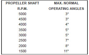
Fig. 5 Maximum Angles And Propeller Shaft Speed


Other materials:
ACC Operation At Stop. Adaptive Cruise Control (ACC) Menu. Display Warnings And Maintenance
ACC Operation At Stop
In the event that the ACC system brings your vehicle to
a standstill while following a target vehicle, if the target
vehicle starts moving within two seconds of your vehicle
coming to a standstill, your vehicle will resume motion
without the need for any driver action.
I ...