Jeep Cherokee (XJ): Diagnosis and testing
Remove the distributor cap and wipe it clean with
a dry lint free cloth. Visually inspect the cap for
cracks, carbon paths, broken towers or damaged
rotor button (Fig. 8) or (Fig. 9). Also check for white
deposits on the inside (caused by condensation entering
the cap through cracks). Replace any cap that
displays charred or eroded terminals. The machined
surface of a terminal end (faces toward rotor) will
indicate some evidence of erosion from normal operation.
Examine the terminal ends for evidence of
mechanical interference with the rotor tip.
1 - BROKEN TOWER Visually inspect the rotor (Fig. 10) for cracks, evidence
of corrosion or the effects of arcing on the
metal tip. Also check for evidence of mechanical
interference with the cap. Some charring is normal
on the end of the metal tip. The silicone-dielectricvarnish-
compound applied to the rotor tip for radio
interference noise suppression, will appear charred.
This is normal. Do not remove the charred compound.
Test the spring for insufficient tension.
Replace a rotor that displays any of these adverse
conditions.
1 - CHARRED OR ERODED TERMINALS
1 - INSUFFICIENT SPRING TENSION TESTING Check the spark plug cable connections for good
contact at the coil(s), distributor cap towers, and
spark plugs. Terminals should be fully seated. The
insulators should be in good condition and should fit
tightly on the coil, distributor and spark plugs. Spark
plug cables with insulators that are cracked or torn
must be replaced.
Clean high voltage ignition cables with a cloth
moistened with a non-flammable solvent. Wipe the
cables dry. Check for brittle or cracked insulation.
When testing secondary cables for damage with an
oscilloscope, follow the instructions of the equipment
manufacturer.
If an oscilloscope is not available, spark plug cables
may be tested as follows: CAUTION: Do not leave any one spark plug cable
disconnected for longer than necessary during testing.
This may cause possible heat damage to the
catalytic converter. Total test time must not exceed
ten minutes.
With the engine running, remove spark plug cable
from spark plug (one at a time) and hold next to a
good engine ground. If the cable and spark plug are
in good condition, the engine rpm should drop and
the engine will run poorly. If engine rpm does not
drop, the cable and/or spark plug may not be operating
properly and should be replaced. Also check
engine cylinder compression.
With the engine not running, connect one end of a
test probe to a good ground. Start the engine and run
the other end of the test probe along the entire
length of all spark plug cables. If cables are cracked
or punctured, there will be a noticeable spark jump
from the damaged area to the test probe. The cable
running from the ignition coil to the distributor cap
can be checked in the same manner. Cracked, damaged
or faulty cables should be replaced with resistance
type cable. This can be identified by the words
ELECTRONIC SUPPRESSION printed on the cable
jacket.
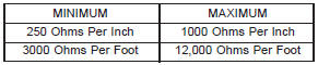
Use an ohmmeter to test for open circuits, excessive
resistance or loose terminals. Remove the distributor
cap from the distributor. Do not remove cables from
cap. Remove cable from spark plug. Connect ohmmeter
to spark plug terminal end of cable and to corresponding
electrode in distributor cap. Resistance
should be 250 to 1000 Ohms per inch of cable. If not,
remove cable from distributor cap tower and connect
ohmmeter to the terminal ends of cable. If resistance
is not within specifications as found in the SPARK
PLUG CABLE RESISTANCE chart, replace the
cable. Test all spark plug cables in this manner. SPARK PLUG CABLE RESISTANCE
To test ignition coil-to-distributor cap cable, do not
remove the cable from the cap. Connect ohmmeter to
rotor button (center contact) of distributor cap and terminal at ignition coil
end of cable. If resistance is
not within specifications as found in the Spark Plug
Cable Resistance chart, remove the cable from the
distributor cap. Connect the ohmmeter to the terminal
ends of the cable. If resistance is not within specifications
as found in the Spark Plug Cable
Resistance chart, replace the cable. Inspect the ignition
coil tower for cracks, burns or corrosion. NORMAL OPERATING The few deposits present on the spark plug will
probably be light tan or slightly gray in color. This is
evident with most grades of commercial gasoline
(Fig. 11). There will not be evidence of electrode
burning. Gap growth will not average more than
approximately 0.025 mm (.001 in) per 3200 km (2000
miles) of operation. Spark plugs that have normal
wear can usually be cleaned, have the electrodes
filed, have the gap set and then be installed.
1 - NORMAL Some fuel refiners in several areas of the United
States have introduced a manganese additive (MMT)
for unleaded fuel. During combustion, fuel with MMT
causes the entire tip of the spark plug to be coated
with a rust colored deposit. This rust color can be
misdiagnosed as being caused by coolant in the combustion
chamber. Spark plug performance may be
affected by MMT deposits. COLD FOULING/CARBON FOULING Cold fouling is sometimes referred to as carbon
fouling. The deposits that cause cold fouling are basically
carbon (Fig. 11). A dry, black deposit on one or
two plugs in a set may be caused by sticking valves
or defective spark plug cables. Cold (carbon) fouling
of the entire set of spark plugs may be caused by a
clogged air cleaner element or repeated short operating
times (short trips). WET FOULING OR GAS FOULING A spark plug coated with excessive wet fuel or oil
is wet fouled. In older engines, worn piston rings,
leaking valve guide seals or excessive cylinder wear
can cause wet fouling. In new or recently overhauled
engines, wet fouling may occur before break-in (normal
oil control) is achieved. This condition can usually
be resolved by cleaning and reinstalling the
fouled plugs. OIL OR ASH ENCRUSTED If one or more spark plugs are oil or oil ash
encrusted (Fig. 12), evaluate engine condition for the
cause of oil entry into that particular combustion
chamber.
ELECTRODE GAP BRIDGING Electrode gap bridging may be traced to loose
deposits in the combustion chamber. These deposits
accumulate on the spark plugs during continuous
stop-and-go driving. When the engine is suddenly
subjected to a high torque load, deposits partially liquefy
and bridge the gap between electrodes (Fig. 13).
This short circuits the electrodes. Spark plugs with
electrode gap bridging can be cleaned using standard
procedures.
1 - GROUND ELECTRODE SCAVENGER DEPOSITS Fuel scavenger deposits may be either white or yellow
(Fig. 14). They may appear to be harmful, but this
is a normal condition caused by chemical additives in
certain fuels. These additives are designed to change
the chemical nature of deposits and decrease spark
plug misfire tendencies. Notice that accumulation on
the ground electrode and shell area may be heavy, but
the deposits are easily removed. Spark plugs with
scavenger deposits can be considered normal in condition
and can be cleaned using standard procedures.
1 - GROUND ELECTRODE COVERED WITH WHITE OR
YELLOW DEPOSITS CHIPPED ELECTRODE INSULATOR A chipped electrode insulator usually results from
bending the center electrode while adjusting the
spark plug electrode gap. Under certain conditions,
severe detonation can also separate the insulator
from the center electrode (Fig. 15). Spark plugs with
this condition must be replaced.
1 - GROUND ELECTRODE PREIGNITION DAMAGE Preignition damage is usually caused by excessive
combustion chamber temperature. The center electrode
dissolves first and the ground electrode dissolves
somewhat latter (Fig. 16). Insulators appear
relatively deposit free. Determine if the spark plug
has the correct heat range rating for the engine.
Determine if ignition timing is over advanced or if
other operating conditions are causing engine overheating.
(The heat range rating refers to the operating
temperature of a particular type spark plug.
Spark plugs are designed to operate within specific
temperature ranges. This depends upon the thickness
and length of the center electrodes porcelain
insulator.) SPARK PLUG OVERHEATING Overheating is indicated by a white or gray center
electrode insulator that also appears blistered (Fig.
17). The increase in electrode gap will be considerably
in excess of 0.001 inch per 2000 miles of operation.
This suggests that a plug with a cooler heat
range rating should be used. Over advanced ignition
timing, detonation and cooling system malfunctions
can also cause spark plug overheating. ELECTRICAL DIAGNOSIS For ignition switch electrical schematics, refer to
Ignition Switch in Group 8W, Wiring Diagrams.
1 - GROUND ELECTRODE STARTING TO DISSOLVE
1 - BLISTERED WHITE OR GRAY COLORED INSULATOR MECHANICAL DIAGNOSIS (KEY DIFFICULT TO
ROTATE) Vehicles equipped with an automatic transmission
and a floor mounted shifter: a cable is
used to connect the interlock device in the steering
column assembly, to the transmission floor shift
lever. This interlock device is used to lock the transmission
shifter in the PARK position when the key
lock cylinder is rotated to the LOCKED or ACCESSORY
position. The interlock device within the steering
column is not serviceable. If repair is necessary,
the steering column assembly must be replaced.
Refer to Group 19, Steering for procedures.
If the ignition key is difficult to rotate to or from
the LOCK or ACCESSORY position, it may not be
the fault of the key cylinder or the steering column
components. The brake transmission shift interlock
cable may be out of adjustment. Refer to Brake
Transmission Shift Interlock Cable Adjustment in
Group 21, Transmissions for adjustment procedures.
Vehicles equipped with an automatic transmission
and a steering column mounted shifter:
an interlock device is located within the steering column.
This interlock device is used to lock the transmission
shifter in the PARK position when the key
lock cylinder is in the LOCKED or ACCESSORY
position. If it is difficult to rotate the key to or from
the LOCK or ACCESSORY position, the interlock
device within the steering column may be defective.
This device is not serviceable. If repair is necessary,
the steering column assembly must be replaced.
Refer to Group 19, Steering for procedures.
Vehicles equipped with a manual transmission
and a floor mounted shifter: on certain models,
a lever is located on the steering column behind
the ignition key lock cylinder. The lever must be
manually operated to allow rotation of the ignition
key lock cylinder to the LOCK or ACCESSORY position.
If it is difficult to rotate the key to the LOCK or
ACCESSORY position, the lever mechanism may be
defective. This mechanism is not serviceable. If
repair is necessary, the steering column assembly
must be replaced. Refer to Group 19, Steering for
procedures.
On other models, the ignition key cylinder must be
depressed to allow it to be rotated into the LOCK or
ACCESSORY position. If it is difficult to rotate the
key to the LOCK or ACCESSORY position, the lock
mechanism within the steering column may be defective.
This mechanism is not serviceable. If repair is
necessary, the steering column assembly must be
replaced. Refer to Group 19, Steering for procedures.Distributor cap-2.5L engine
Fig. 8 Cap Inspection-External-Typical
2 - DISTRIBUTOR CAP
3 - CARBON PATH
4 - CRACKDistributor rotor-2.5L engine
Fig. 9 Cap Inspection-Internal-Typical
2 - WORN OR DAMAGED ROTOR BUTTON
3 - CARBON PATH
Fig. 10 Rotor Inspection-Typical
2 - CRACKS
3 - EVIDENCE OF PHYSICAL CONTACT WITH CAP
4 - ROTOR TIP CORRODEDSpark plug cables
Spark plug conditions
Fig. 11 Normal Operation and Cold (Carbon) Fouling
2 - DRY BLACK DEPOSITS
3 - COLD (CARBON) FOULING
Fig. 12 Oil or Ash Encrusted
Fig. 13 Electrode Gap Bridging
2 - DEPOSITS
3 - CENTER ELECTRODE
Fig. 14 Scavenger Deposits
2 - CENTER ELECTRODE
Fig. 15 Chipped Electrode Insulator
2 - CENTER ELECTRODE
3 - CHIPPED INSULATORIgnition switch and key lock
cylinder
Fig. 16 Preignition Damage
2 - CENTER ELECTRODE DISSOLVED
Fig. 17 Spark Plug Overheating


Other materials:
Electronic vehicle information center (evic)
The Electronic Vehicle Information Center (EVIC) features
a driver-interactive display that is located in the
instrument cluster.
Electronic Vehicle Information Center (EVIC) Location
The EVIC Menu items consist of the following:
Speedometer
Vehicle Info
Driver Assist
Fuel Economy
...