Jeep Cherokee (XJ): Diagnosis and testing
The horn relay (Fig. 2) is located in the junction
block on the right cowl side inner panel below the
instrument panel in the passenger compartment. If a
problem is encountered with a continuously sounding
horn, it can usually be quickly resolved by removing
the horn relay from the junction block until further
diagnosis is completed. Refer to Junction Block in
the Contents of Group 8W - Wiring Diagrams for
horn relay identification and location. For complete
circuit diagrams, refer to Horn/Cigar Lighter in the
Contents of Group 8W - Wiring Diagrams.
WARNING: ON VEHICLES EQUIPPED WITH AIRBAGS,
REFER TO GROUP 8M - PASSIVE
RESTRAINT SYSTEMS BEFORE ATTEMPTING ANY
STEERING WHEEL, STEERING COLUMN, OR
INSTRUMENT PANEL COMPONENT DIAGNOSIS OR
SERVICE. FAILURE TO TAKE THE PROPER PRECAUTIONS
COULD RESULT IN ACCIDENTAL AIRBAG
DEPLOYMENT AND POSSIBLE PERSONAL
INJURY.
(1) Remove the horn relay from the junction block.
Refer to Horn Relay in the Removal and Installation
section of this group for the procedures.
(2) A relay in the de-energized position should
have continuity between terminals 87A and 30, and
no continuity between terminals 87 and 30. If OK, go
to Step 3. If not OK, replace the faulty relay.
(3) Resistance between terminals 85 and 86 (electromagnet)
should be 75 6 5 ohms. If OK, go to Step
4. If not OK, replace the faulty relay.
(4) Connect a battery to terminals 85 and 86.
There should now be continuity between terminals
30 and 87, and no continuity between terminals 87A
and 30. If OK, perform the Relay Circuit Test that
follows. If not OK, replace the faulty relay.
RELAY CIRCUIT TEST (1) The relay common feed terminal cavity (30) is
connected to battery voltage and should be hot at all
times. If OK, go to Step 2. If not OK, repair the open
circuit to the fuse in the junction block as required.
(2) The relay normally closed terminal (87A) is
connected to terminal 30 in the de-energized position,
but is not used for this application. Go to Step 3.
(3) The relay normally open terminal (87) is connected
to the common feed terminal (30) in the energized
position. This terminal supplies battery voltage
to the horn(s). There should be continuity between
the cavity for relay terminal 87 and the horn relay
output circuit cavity of each horn wire harness connector
at all times. If OK, go to Step 4. If not OK,
repair the open circuit to the horn(s) as required.
(4) The coil battery terminal (86) is connected to
the electromagnet in the relay. It is connected to battery
voltage and should be hot at all times. Check for
battery voltage at the cavity for relay terminal 86. If
OK, go to Step 5. If not OK, repair the open circuit to
the fuse in the junction block as required.
(5) The coil ground terminal (85) is connected to
the electromagnet in the relay. It is grounded
through the horn switch when the horn switch is
depressed. On vehicles equipped with the Remote
Keyless Entry (RKE) system, the horn relay coil
ground terminal can also be grounded by the RKE
receiver in response to certain inputs related to the
RKE system. Check for continuity to ground at the
cavity for relay terminal 85. There should be continuity
with the horn switch depressed, and no continuity
with the horn switch released. If not OK, refer
to Horn Switch in the Diagnosis and Testing section
of this group. For complete circuit diagrams, refer to Horn/Cigar
Lighter in the Contents of Group 8W - Wiring
Diagrams.
WARNING: ON VEHICLES EQUIPPED WITH AIRBAGS,
REFER TO GROUP 8M - PASSIVE
RESTRAINT SYSTEMS BEFORE ATTEMPTING ANY
STEERING WHEEL, STEERING COLUMN, OR
INSTRUMENT PANEL COMPONENT DIAGNOSIS OR
SERVICE. FAILURE TO TAKE THE PROPER PRECAUTIONS
COULD RESULT IN ACCIDENTAL AIRBAG
DEPLOYMENT AND POSSIBLE PERSONAL
INJURY.
(1) Disconnect and isolate the battery negative
cable. Remove the knee blocker from the instrument
panel.
(2) Check for continuity between the metal steering
column jacket and a good ground. There should
be continuity. If OK, go to Step 3. If not OK, refer to
Steering Column in the Removal and Installation
section of Group 19 - Steering for proper installation
of the steering column.
(3) Remove the driver side airbag module from the
steering wheel. Disconnect the horn switch wire harness
connectors from the driver side airbag module.
(4) Remove the horn relay from the junction block.
Check for continuity between the steering column
half of the horn switch feed wire harness connector
and a good ground. There should be no continuity. If
OK, go to Step 5. If not OK, repair the shorted horn
relay control circuit to the horn relay in the junction
block as required.
(5) Check for continuity between the steering column
half of the horn switch feed wire harness connector
and the horn relay control circuit cavity for
the horn relay in the junction block. There should be
continuity. If OK, go to Step 6. If not OK, repair the
open horn relay control circuit to the horn relay in
the junction block as required.
(6) Check for continuity between the horn switch
feed wire and the horn switch ground wire on the
driver side airbag module. There should be no continuity.
If OK, go to Step 7. If not OK, replace the
faulty horn switch.
(7) Depress the center of the driver side airbag
module trim cover and check for continuity between
the horn switch feed wire and the horn switch
ground wire on the driver side airbag module. There
should now be continuity. If not OK, replace the
faulty horn switch. For complete circuit diagrams, refer to Horn/Cigar
Lighter in the Contents of Group 8W - Wiring
Diagrams.
(1) Measure the resistance between the horn(s)
mounting bracket(s) and a good ground. There should
be no measurable resistance. If OK, go to Step 2. If
not OK, clean and tighten the horn mounting hardware
as required.
(2) Disconnect the wire harness connector(s) from
the horn connector receptacle(s). Check for battery
voltage at the horn relay output circuit cavity of the
horn(s) wire harness connector(s). There should be
zero volts. If OK, go to Step 3. If not OK, repair the
shorted horn relay output circuit or replace the
faulty horn relay as required.
(3) Depress the horn switch. There should now be
battery voltage at the horn relay output circuit cavity
of the horn(s) wire harness connector(s). If OK,
replace the faulty horn(s). If not OK, repair the open
horn relay output circuit to the horn relay as
required.Horn relay
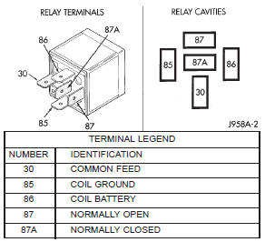
Fig. 2 Horn RelayHorn switch
Horn


Other materials:
Maintenance schedules
SERVICE PROCEDURES
DESCRIPTION
Service and maintenance procedures for components
and systems listed in Schedule "A" or "B" can
be found by using the Group Tab Locator index at
the front of this manual. If it is not clear which
group contains the information needed, refer to the
index at the b ...