Jeep Cherokee (XJ): Diagnosis and testing
FRONT For circuit descriptions and diagrams, refer to
8W-53 - Wipers in Group 8W - Wiring Diagrams. WARNING: ON VEHICLES EQUIPPED WITH AIRBAGS,
REFER TO GROUP 8M - PASSIVE
RESTRAINT SYSTEMS BEFORE ATTEMPTING ANY
STEERING WHEEL, STEERING COLUMN, OR
INSTRUMENT PANEL COMPONENT DIAGNOSIS OR
SERVICE. FAILURE TO TAKE THE PROPER PRECAUTIONS
COULD RESULT IN ACCIDENTAL AIRBAG
DEPLOYMENT AND POSSIBLE PERSONAL
INJURY.
(1) Check the circuit breaker in the junction block.
If OK, go to Step 2. If not OK, replace the faulty circuit
breaker.
(2) Disconnect and isolate the battery negative
cable. Unplug the windshield wiper switch wire harness
connector. Connect the battery negative cable.
Turn the ignition switch to the On position. Check
for battery voltage at the fused ignition switch output
(run/acc) circuit cavity of the wiper switch wire
harness connector. If OK, go to Step 3. If not OK,
repair the open circuit to the junction block as
required.
(3) If the problem being diagnosed involves only
the pulse wipe, wipe-after-wash, or intermittent wipe
modes, go to Step 4. If not, go to Step 5. (4) Turn the ignition switch to the Off position.
Disconnect and isolate the battery negative cable.
Check for continuity between the ground circuit cavity
of the wiper switch wire harness connector and a
good ground. There should be continuity. If OK,
replace the faulty switch. If not OK, repair the open
circuit to ground as required.
(5) Turn the ignition switch to the Off position.
Disconnect and isolate the battery negative cable.
Remove the windshield wiper and washer switch and
check the switch continuity. See Wiper Switch and
Washer Switch in the Diagnosis and Testing section
of this group for the procedures. If OK, go to Step 6.
If not OK, replace the faulty switch.
(6) Unplug the windshield wiper motor wire harness
connector. Check for continuity between the
ground circuit cavity in the body half of the wiper
motor wire harness connector and a good ground.
There should be continuity. If OK, go to Step 7. If not
OK, repair the open circuit to ground as required.
(7) Connect the battery negative cable. Turn the
ignition switch to the On position. Check for battery
voltage at the fused ignition switch output (run/acc)
circuit cavity in the body half of the wiper motor wire
harness connector. If OK, go to Step 8. If not OK,
repair the open circuit to the junction block as
required.
(8) Turn the ignition switch to the Off position.
Disconnect and isolate the battery negative cable.
With the windshield wiper and washer switch wire
harness connector still unplugged, check the cavities
for each of the following circuits in the body half of
the wiper motor wire harness connector for continuity
to ground. In each case, there should be no continuity.
If OK, go to Step 9. If not OK, repair the short
circuit as required. (9) Check for continuity between the cavities in
the body half of the wiper motor wire harness connector
and the cavities in the windshield wiper and
washer switch wire harness connector for each of the
following circuits. In each case, there should be continuity.
If OK, replace the faulty wiper motor. If not
OK, repair the open circuit as required. REAR For circuit descriptions and diagrams, refer to
8W-53 - Wipers in Group 8W - Wiring Diagrams.
WARNING: ON VEHICLES EQUIPPED WITH AIRBAGS,
REFER TO GROUP 8M - PASSIVE
RESTRAINT SYSTEMS BEFORE ATTEMPTING ANY
STEERING WHEEL, STEERING COLUMN, OR
INSTRUMENT PANEL COMPONENT DIAGNOSIS OR
SERVICE. FAILURE TO TAKE THE PROPER PRECAUTIONS
COULD RESULT IN ACCIDENTAL AIRBAG
DEPLOYMENT AND POSSIBLE PERSONAL
INJURY.
(1) Check the fuse in the junction block. If OK, go
to Step 2. If not OK, repair the shorted circuit or
component as required and replace the faulty fuse.
(2) Disconnect and isolate the battery negative
cable. Remove the accessory switch bezel and unplug
the wire harness connector from the rear wiper and
washer switch. Connect the battery negative cable.
Turn the ignition switch to the On position. Check
for battery voltage at the fused ignition switch output
circuit cavity of the rear wiper and washer
switch wire harness connector. If OK, go to Step 3. If
not OK, repair the open circuit to the junction block
as required.
(3) Turn the ignition switch to the Off position.
Disconnect and isolate the battery negative cable.
Check for continuity between the ground circuit cavity
of the rear wiper and washer switch wire harness
connector and a good ground. There should be continuity.
If OK, go to Step 4. If not OK, repair the open
circuit to ground as required.
(4) Test the rear wiper and washer switch continuity.
See Wiper Switch and Washer Switch in the
Diagnosis and Testing section of this group for the
procedures. If OK, go to Step 5. If not OK, replace
the faulty switch.
(5) Remove the liftgate trim panel and unplug the
rear wiper motor wire harness connector. Connect
the battery negative cable. Turn the ignition switch
to the On position. Check for battery voltage at the
fused ignition switch output (run) circuit cavity of
the rear wiper motor wire harness connector. If OK,
go to Step 6. If not OK, repair the open circuit to the
junction block as required.
(6) Turn the ignition switch to the Off position.
Disconnect and isolate the battery negative cable.
Check for continuity between the ground circuit cavity
of the rear wiper motor wire harness connector
and a good ground. There should be continuity. If
OK, go to Step 7. If not OK, repair the open circuit to
ground as required.
(7) Check for continuity between the rear wiper
motor control circuit cavity of the rear wiper motor
wire harness connector and a good ground. There
should be no continuity. If OK, go to Step 8. If not
OK, repair the short circuit as required.
(8) Check for continuity between the rear wiper
motor control circuit cavities of the rear wiper motor
wire harness connector and the rear wiper and
washer switch wire harness connector. There should be continuity. If OK, replace
the faulty rear wiper
motor. If not OK, repair the open circuit as required. FRONT The diagnosis found here addresses an inoperative
front washer pump. If the washer pump operates,
but no washer fluid is emitted from the washer nozzles,
be certain to check the fluid level in the reservoir.
Check for ice or other foreign material in the
reservoir, and for pinched, disconnected, broken, or
incorrectly routed washer system plumbing. For circuit
descriptions and diagrams, refer to 8W-53 - Wipers
in Group 8W - Wiring Diagrams. WARNING: ON VEHICLES EQUIPPED WITH AIRBAGS,
REFER TO GROUP 8M - PASSIVE
RESTRAINT SYSTEMS BEFORE ATTEMPTING ANY
STEERING WHEEL, STEERING COLUMN, OR
INSTRUMENT PANEL COMPONENT DIAGNOSIS OR
SERVICE. FAILURE TO TAKE THE PROPER PRECAUTIONS
COULD RESULT IN ACCIDENTAL AIRBAG
DEPLOYMENT AND POSSIBLE PERSONAL
INJURY.
(1) Turn the ignition switch to the On position.
Turn the wiper switch to the Low or High speed position.
Check whether the wipers operate. If OK, go to
Step 2. If not OK, see the Wiper System diagnosis in
this group.
(2) Turn the ignition switch to the Off position.
Disconnect and isolate the battery negative cable.
Unplug the front washer pump wire harness connector.
Check for continuity between the ground circuit
cavity of the front washer pump wire harness connector
and a good ground. There should be continuity. If
OK, go to Step 3. If not OK, repair the open circuit to
ground as required.
(3) Connect the battery negative cable. Turn the
ignition switch to the On position. Check for battery
voltage at the front washer switch output circuit cavity
of the front washer pump wire harness connector
while actuating the washer switch. If OK, replace the
faulty washer pump. If not OK, go to Step 4.
(4) Turn the ignition switch to the Off position.
Disconnect and isolate the battery negative cable.
Unplug the windshield wiper/washer switch wire
harness connector. Check for continuity between the
front washer switch output circuit cavity of the front
washer pump wire harness connector and a good
ground. There should be no continuity. If OK, go to
Step 5 If not OK, repair the short circuit as required.
(5) Check for continuity between the front washer
switch output circuit cavities of the front washer
pump wire harness connector and the wiper/washer
switch wire harness connector. There should be continuity.
If OK, replace the faulty switch. If not OK,
repair the open circuit as required. REAR The diagnosis found here addresses an inoperative
rear washer pump. If the washer pump operates, but
no washer fluid is emitted from the washer nozzle, be
certain to check the fluid level in the reservoir. Check
for ice or other foreign material in the reservoir, and
for pinched, disconnected, broken, or incorrectly
routed washer system plumbing. For circuit descriptions
and diagrams, refer to 8W-53 - Wipers in Group
8W - Wiring Diagrams. WARNING: ON VEHICLES EQUIPPED WITH AIRBAGS,
REFER TO GROUP 8M - PASSIVE
RESTRAINT SYSTEMS BEFORE ATTEMPTING ANY
STEERING WHEEL, STEERING COLUMN, OR
INSTRUMENT PANEL COMPONENT DIAGNOSIS OR
SERVICE. FAILURE TO TAKE THE PROPER PRECAUTIONS
COULD RESULT IN ACCIDENTAL AIRBAG
DEPLOYMENT AND POSSIBLE PERSONAL
INJURY.
(1) Turn the ignition switch to the On position.
Place the rear wiper/washer switch in the Wipe position.
Check whether the rear wiper is operating. If
OK, go to Step 2. If not OK, see the Wiper System
diagnosis in this group.
(2) Turn the ignition switch to the Off position.
Disconnect and isolate the battery negative cable.
Unplug the rear washer pump wire harness connector.
Check for continuity between the ground circuit
cavity of the rear washer pump wire harness connector
and a good ground. There should be continuity. If
OK, go to Step 3. If not OK, repair the open circuit to
ground as required.
(3) Connect the battery negative cable. Turn the
ignition switch to the On position. Check for battery
voltage at the rear washer motor control circuit cavity
of the rear washer pump wire harness connector
while the rear washer switch is actuated. If OK,
replace the faulty pump. If not OK, go to Step 4.
(4) Turn the ignition switch to the Off position.
Disconnect and isolate the battery negative cable.
Unplug the rear wiper/washer switch wire harness
connector. Check for continuity between the rear
washer motor control circuit cavity of the rear
washer pump wire harness connector and a good
ground. There should be no continuity. If OK, go to
Step 5. If not OK, repair the short circuit as
required.
(5) Check for continuity between the rear washer
motor control circuit cavities of the rear washer
pump wire harness connector and the rear wiper/
washer switch wire harness connector. There should be continuity. If OK, replace
the faulty switch. If not
OK, repair the open circuit as required. FRONT Perform the diagnosis for the front wiper system
and/or washer system as described in this group
before testing the front wiper and washer switch. For
circuit descriptions and diagrams, see 8W-53 - Wipers
in Group 8W - Wiring Diagrams.
WARNING: ON VEHICLES EQUIPPED WITH AIRBAGS,
REFER TO GROUP 8M - PASSIVE
RESTRAINT SYSTEMS BEFORE ATTEMPTING ANY
STEERING WHEEL, STEERING COLUMN, OR
INSTRUMENT PANEL COMPONENT DIAGNOSIS OR
SERVICE. FAILURE TO TAKE THE PROPER PRECAUTIONS
COULD RESULT IN ACCIDENTAL AIRBAG
DEPLOYMENT AND POSSIBLE PERSONAL
INJURY.
(1) Disconnect and isolate the battery negative
cable.
(2) Remove the front wiper and washer switch
from the steering column and unplug the wire harness
connector from the switch.
(3) Using an ohmmeter, perform the switch continuity
checks at the switch terminals as shown in the
Windshield Wiper Switch and Washer Switch Continuity
chart (Fig. 2).
(4) If the switch fails any of the continuity checks,
replace the faulty switch. If the switch is OK, repair
the wiper system and/or washer system wire harness
circuits as required. REAR Perform the diagnosis for the rear wiper system
and/or washer system as described in this group
before testing the rear wiper and washer switch. For
circuit descriptions and diagrams, see 8W-53 - Wipers
in Group 8W - Wiring Diagrams. WARNING: ON VEHICLES EQUIPPED WITH AIRBAGS,
REFER TO GROUP 8M - PASSIVE
RESTRAINT SYSTEMS BEFORE ATTEMPTING ANY
STEERING WHEEL, STEERING COLUMN, OR
INSTRUMENT PANEL COMPONENT DIAGNOSIS OR
SERVICE. FAILURE TO TAKE THE PROPER PRECAUTIONS
COULD RESULT IN ACCIDENTAL AIRBAG
DEPLOYMENT AND POSSIBLE PERSONAL
INJURY.
(1) Remove the accessory switch bezel from the
instrument panel and unplug the rear wiper and
washer switch wire harness connector.
(2) Using an ohmmeter, check the rear wiper and
washer switch continuity at the switch terminals as
shown in the Rear Wiper Switch and Washer Switch
Continuity chart (Fig. 3).
(3) If the switch fails any of the continuity checks,
replace the faulty switch. If the switch is OK, repair
the rear wiper system and/or washer system wire
harness circuits as required.Wiper system
Washer system
Wiper switch and washer switch
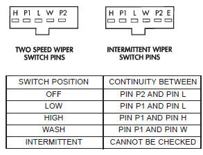
Fig. 2 Windshield Wiper Switch and Washer Switch Continuity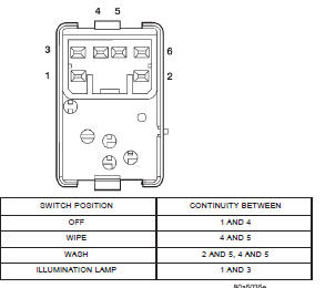
Fig. 3 Rear Wiper Switch and Washer Switch Continuity


Other materials:
Drive axle assembly. Tube axle assembly. Axle shaft-cardan U-joint
Drive axle assembly
REMOVAL
Raise and support the vehicle.
Position a suitable lifting device under the
axle.
Secure axle to device.
Remove the wheels and tires.
Remove the brake rotors and calipers from the
axle. Refer to Group 5, Brakes, for proper pro ...