Jeep Cherokee (XJ): Diagnosis and testing
Before any testing of the power seat system is
attempted, the battery should be fully-charged and
all wire harness connections and pins cleaned and
tightened to ensure proper continuity and grounds.
For circuit descriptions and diagrams, refer to 8W-63
- Power Seat in Group 8W - Wiring Diagrams.
With the dome lamp on, apply the power seat
switch in the direction of the failure. If the dome
lamp dims, the seat may be jamming. Check under
and behind the seat for binding or obstructions. If
the dome lamp does not dim, proceed with testing of
the individual components and circuits. For circuit descriptions and diagrams, refer to
8W-63 - Power Seat in Group 8W - Wiring Diagrams.
(1) Locate the correct circuit breaker in the junction
block. Pull out the circuit breaker slightly, but
be certain that the circuit breaker terminals still contact
the terminals in the junction block cavities.
(2) Connect the negative lead of a 12-volt DC voltmeter
to a good ground.
(3) With the voltmeter positive lead, check both
terminals of the circuit breaker for battery voltage.
If only one terminal has battery voltage, the circuit
breaker is faulty and must be replaced. If neither terminal
has battery voltage, repair the open circuit
from the Power Distribution Center (PDC) as
required. For circuit descriptions and diagrams, refer to
8W-63 - Power Seat in Group 8W - Wiring Diagrams.
Operate the power seat switch to move all three
seat motors in each direction. The seat should move
in each of the selected directions. If the power seat
adjuster fails to operate in only one direction, move
the adjuster a short distance in the opposite direction
and test again to be certain that the adjuster is not
at its travel limit. If the power seat adjuster still
fails to operate in only one direction, see Power Seat
Switch in the Diagnosis and Testing section of this
group. If the power seat adjuster fails to operate in
more than one direction, proceed as follows:
(1) Test the circuit breaker in the junction block as
described in this group. If OK, go to Step 2. If not
OK, replace the faulty circuit breaker.
(2) Remove the power seat switch from the seat.
Check for battery voltage at the fused B(+) circuit
cavity of the power seat switch wire harness connector.
If OK, go to Step 3. If not OK, repair the open
circuit to the junction block as required.
(3) Check for continuity between the ground circuit
cavity of the power seat switch wire harness connector
and a good ground. There should be
continuity. If OK, go to Step 4. If not OK, repair the
open circuit to ground as required.
(4) Test the power seat switch as described in this
group. If the switch tests OK, check the wire harness
for the inoperative power seat motor(s) between the
power seat switch and the motor for shorts or opens.
If the circuits check OK, replace the faulty power
seat adjuster and motors assembly. If the circuits are
not OK, repair the wire harness as required. For circuit descriptions and diagrams, refer to
8W-63 - Power Seat in Group 8W - Wiring Diagrams.
(1) Disconnect and isolate the battery negative
cable.
(2) Remove the power seat switch from the power
seat.
(3) Use an ohmmeter to test the continuity of the
power seat switches in each position. See the Power
Seat Switch Continuity chart (Fig. 1). If OK, see the
diagnosis for the Power Seat Adjuster and Motors in
this group. If not OK, replace the faulty power seat
switch module.
Power seat system
Circuit breaker
Power seat adjuster and motors
Power seat switch
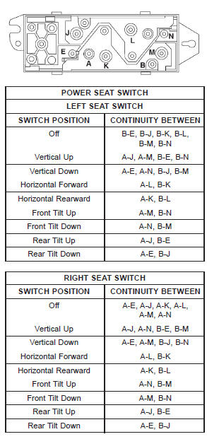
Fig. 1 Power Seat Switch Continuity


Other materials:
Driver side airbag module trim
cover
The horn switch is integral to the driver side airbag
module trim cover. If either component is faulty
or damaged, the entire driver side airbag module
trim cover and horn switch unit must be replaced.
WARNING:
THE AIRBAG SYSTEM IS A SENSITIVE, COMPLEX
ELECTROMECHANICAL UNIT. BEFORE
...