Jeep Cherokee (XJ): Diagnosis and testing
For circuit descriptions and diagrams, refer to
8W-60 - Power Windows in Group 8W - Wiring Diagrams. ALL WINDOWS INOPERATIVE (1) Check the circuit breaker in the junction block,
as described in this group. If OK, go to Step 2. If not
OK, replace the faulty circuit breaker.
(2) Disconnect and isolate the battery negative
cable. Remove the driver side front door trim panel
and unplug the Driver Door Module (DDM) wire harness
connectors from the DDM. Check for continuity
between the ground circuit cavity of the 8-way DDM
wire harness connector and a good ground. If OK, go
to Step 3. If not OK, repair the circuit to ground as
required.
(3) Connect the battery negative cable. Turn the
ignition switch to the On position. Check for battery
voltage at the master switch power feed (run/acc) circuit
cavity of the 12-way DDM wire harness connector.
If OK, see the diagnosis for the Door Module in
this group. If not OK, repair the open circuit to the
circuit breaker in the junction block as required. ONE WINDOW INOPERATIVE The window glass must be free to slide up and
down for the power window motor to function properly.
If the glass is not free to move up and down, the
motor will overload and trip the integral circuit
breaker. To determine if the glass is free, disconnect
the regulator plate from the glass. Then slide the
window up and down by hand.
There is an alternate method to check if the glass
is free. Position the glass between the up and down
stops. Then, shake the glass in the door. Check that the glass can be moved
slightly from side to side,
front to rear, and up and down. Then check that the
glass is not bound tight in the tracks. If the glass is
free, proceed with the diagnosis that follows. If the
glass is not free, refer to Group 23 - Body for the
door window glass and hardware service and adjustment
procedures.
(1) Check the power window switch continuity as
described in the diagnosis for the Door Module (front
doors) or Power Window Switch (rear doors) in this
group. If OK and the driver side front window is
inoperative, see the Power Window Motor diagnosis
in this group. If OK and the inoperative window is
other than the driver side front, go to Step 2. If not
OK, replace the faulty door module or switch.
(2) Refer to the circuit diagrams in 8W-60 - Power
Windows in Group 8W - Wiring Diagrams. Check the
continuity in each circuit between the inoperative
Passenger Door Module (PDM) or power window
switch wire harness connector cavities and the corresponding
Driver Door Module (DDM) wire harness
connector cavities. If OK, see the diagnosis for the
Power Window Motor in this group. If not OK, repair
the open circuit(s) as required.
NOTE: All individual power window switches
receive their battery and ground feeds through the
Driver Door Module (DDM) and wire harness connectors. For circuit descriptions and diagrams, refer to
8W-60 - Power Windows in Group 8W - Wiring Diagrams.
(1) Locate the circuit breaker in the junction block.
Pull out the circuit breaker slightly, but be certain
that the circuit breaker terminals still contact the
terminals in the junction block cavities.
(2) Connect the negative lead of a 12-volt DC voltmeter
to a good ground.
(3) With the voltmeter positive lead, check both
terminals of the circuit breaker for battery voltage.
If only one terminal has battery voltage, the circuit
breaker is faulty and must be replaced. If neither terminal
has battery voltage, repair the open circuit
from the Power Distribution Center (PDC) as
required. If the circuit breaker checks OK, but no
power windows operate, see Power Window System
in the Diagnosis and Testing section of this group. The Driver Door Module (DDM) contains the master
switches and the lockout switch in the power window
system. The DDM also contains an integrated
circuit to support the one-touch down feature of the
driver side front door power window. Remember that
the passenger side front door power window switch
and, on four-door models, the rear door power window
switches get their battery current through the
power window lockout switch in the Driver Door
Module (DDM). In addition, each individual power
window switch gets its ground through the master
switch in the DDM.
The one-touch down feature circuitry within the
DDM will not operate the power window motor if the
door glass, window regulator, or gearbox mechanism
are stuck, obstructed, or binding. If the driver side
front door power window operates as designed, but
the one-touch down feature is inoperative, replace
the faulty DDM.
If the problem being diagnosed is an inoperative
power window switch illumination lamp, but the
power window switch operates as designed, replace
the faulty door module. For circuit descriptions and
diagrams, refer to 8W-60 - Power Windows in Group
8W - Wiring Diagrams.
(1) Disconnect and isolate the battery negative
cable. Remove the front door trim panel and unplug
the door module wire harness connectors from the
door module.
(2) Check the door module power window switch
and/or power window lockout switch continuity in
each position, as shown in the proper chart (Fig. 1)
or (Fig. 2). If OK, see the Power Window Motor diagnosis
in this group. If not OK, replace the faulty door
module.
The diagnosis found here applies only to the rear
door power window switches. For diagnosis of the
front door power window switches, see Door Module
in this group. If the problem being diagnosed is an
inoperative power window switch illumination lamp,
but the power window switch operates as designed,
replace the faulty switch. For circuit descriptions and
diagrams, refer to 8W-60 - Power Windows in Group
8W - Wiring Diagrams.
(1) Disconnect and isolate the battery negative
cable.
(2) Remove the power window switch from the
rear door trim panel.
(3) Check the power window switch continuity in
each position as shown in the Rear Door Power Window
Switch Continuity chart (Fig. 3). If OK, see the
Power Window Motor diagnosis in this group. If not
OK, replace the faulty switch.
For circuit descriptions and diagrams, refer to
8W-60 - Power Windows in Group 8W - Wiring Diagrams.
Before you proceed with this diagnosis, confirm
proper switch operation. See the Door Module
and/or Power Window Switch diagnosis in this group.
(1) Disconnect and isolate the battery negative
cable. Remove the trim panel from the door with the
inoperative power window.
(2) Unplug the power window motor wire harness
connector. Apply 12 volts across the motor terminals
to check its operation in one direction. Reverse the
connections across the motor terminals to check the
operation in the other direction. Remember, if the
window is in the full up or full down position, the
motor will not operate in that direction by design. If
OK, repair the circuits from the power window motor
to the door module or the power window switch as
required. If not OK, replace the faulty motor.
(3) If the motor operates in both directions, check
the operation of the window glass and lift mechanism
through its complete up and down travel. There
should be no binding or sticking of the window glass
or lift mechanism through the entire travel range. If
not OK, refer to Group 23 - Body to check the window
glass, tracks, and regulator for sticking, binding,
or improper adjustment.Power window system
Circuit breaker
Door module
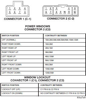
Fig. 1 DDM Power Window Switch Continuity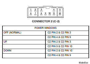
Fig. 2 PDM Power Window Switch ContinuityPower window switch
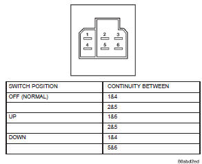
Fig. 3 Rear Door Power Window Switch ContinuityPower window motor


Other materials:
Disassembly and assembly. Specifications
Disassembly and assembly
HYDRAULIC CONTROL UNIT/CONTROLLER
ANTILOCK BRAKE
DISASSEMBLY
(1) Remove pump motor connector from the CAB.
(2) Remove CAB mounting screws from the HCU
(Fig. 13).
(3) Remove CAB from the HCU.
Fig. 13 CAB Mounting Screws
1 - MOUNTING SCREWS
2 - CAB
ASSEMBLY
...