Jeep Cherokee (XJ): Diagnosis and testing
Use this test in conjunction with the Fuel Pump
Capacity Test, Fuel Pressure Leak Down Test and
Fuel Pump Amperage Test found elsewhere in this
group.
Check Valve Operation: The electric fuel pump
outlet contains a one-way check valve to prevent fuel
flow back into the tank and to maintain fuel supply
line pressure (engine warm) when pump is not operational.
It is also used to keep the fuel supply line
full of gasoline when pump is not operational. After
the vehicle has cooled down, fuel pressure may drop
to 0 psi (cold fluid contracts), but liquid gasoline will
remain in fuel supply line between the check valve
and fuel injectors. Fuel pressure that has
dropped to 0 psi on a cooled down vehicle
(engine off) is a normal condition. When the electric
fuel pump is activated, fuel pressure should
immediately (1-2 seconds) rise to specification.
All fuel systems are equipped with a fuel tank
module mounted, combination fuel filter/fuel pressure
regulator. The fuel pressure regulator is not controlled
by engine vacuum.
WARNING: THE FUEL SYSTEM IS UNDER CONSTANT
FUEL PRESSURE EVEN WITH THE ENGINE
OFF. BEFORE DISCONNECTING FUEL LINE AT
FUEL RAIL, THIS PRESSURE MUST BE RELEASED.
REFER TO THE FUEL SYSTEM PRESSURE
RELEASE PROCEDURE.
(1) Remove protective cap at fuel rail test port.
Connect the 0-414 kPa (0-60 psi) fuel pressure gauge (from gauge set 5069) to
test port pressure fitting on
fuel rail (Fig. 7). The DRB III Scan Tool along
with the PEP module, the 500 psi pressure
transducer, and the transducer-to-test port
adapter may also be used in place of the fuel
pressure gauge.
1 - SERVICE (TEST) PORT (2) Start and warm engine and note pressure
gauge reading. Fuel pressure should be 339 kPa 6 34
kPa (49.2 psi 6 5 psi) at idle.
(3) If engine runs, but pressure is below 44.2 psi,
check for a kinked fuel supply line somewhere
between fuel rail and fuel pump module. If line is not
kinked, but specifications for either the Fuel Pump
Capacity, Fuel Pump Amperage or Fuel Pressure
Leak Down Tests were not met, replace fuel pump
module assembly. Refer to Fuel Pump Module
Removal/Installation.
(4) If operating pressure is above 54.2 psi, electric
fuel pump is OK, but fuel pressure regulator is defective.
Replace fuel filter/fuel pressure regulator. Refer
to Fuel Filter/Fuel Pressure Regulator Removal/Installation
for more information.
(5) Install protective cap to fuel rail test port. Before performing this test, verify fuel pump
pressure. Refer to Fuel Pump Pressure Test.
Use this test in conjunction with the Fuel Pressure
Leak Down Test.
(1) Release fuel system pressure. Refer to Fuel
Pressure Release Procedure.
(2) Disconnect fuel supply line at fuel rail. Refer to
Quick-Connect Fittings. Some engines may require
air cleaner housing removal before line disconnection.
(3) Obtain correct Fuel Line Pressure Test Adapter
Tool Hose. Tool number 6539 is used for 5/16" fuel
lines and tool number 6631 is used for 3/8" fuel lines.
(4) Connect correct Fuel Line Pressure Test
Adapter Tool Hose into disconnected fuel supply line.
Insert other end of Adaptor Tool Hose into a graduated
container.
(5) Remove fuel fill cap.
(6) To activate fuel pump and pressurize system,
obtain DRB scan tool and actuate ASD Fuel System
Test.
(7) A good fuel pump will deliver at least 1/4 liter
of fuel in 7 seconds. Do not operate fuel pump for
longer than 7 seconds with fuel line disconnected as
fuel pump module reservoir may run empty.
(a) If capacity is lower than specification, but
fuel pump can be heard operating through fuel fill
cap opening, check for a kinked/damaged fuel supply
line somewhere between fuel rail and fuel
pump module.
(b) If line is not kinked/damaged, and fuel pressure
is OK, but capacity is low, replace fuel filter/
fuel pressure regulator. The filter/regulator may be
serviced separately on certain applications. Refer
to Fuel Filter/Fuel Pressure Regulator Removal/Installation
for additional information.
(c) If both fuel pressure and capacity are low,
replace fuel pump module assembly. Refer to Fuel
Pump Module Removal/Installation. Use this test in conjunction with the Fuel Pump
Pressure Test and Fuel Pump Capacity Test.
Check Valve Operation: The electric fuel pump
outlet contains a one-way check valve to prevent fuel
flow back into the tank and to maintain fuel supply
line pressure (engine warm) when pump is not operational.
It is also used to keep the fuel supply line
full of gasoline when pump is not operational. After
the vehicle has cooled down, fuel pressure may drop
to 0 psi (cold fluid contracts), but liquid gasoline will
remain in fuel supply line between the check valve
and fuel injectors. Fuel pressure that has
dropped to 0 psi on a cooled down vehicle
(engine off) is a normal condition. When the electric
fuel pump is activated, fuel pressure should
immediately (1-2 seconds) rise to specification.
Abnormally long periods of cranking to restart a
hot engine that has been shut down for a short
period of time may be caused by: (1) Disconnect the fuel inlet line at fuel rail. Refer
to Fuel Tubes/Lines/Hoses and Clamps in this section
of the group for procedures. On some engines, air cleaner housing removal may be
necessary before
fuel line disconnection.
(2) Obtain correct Fuel Line Pressure Test Adapter
Tool Hose. Tool number 6539 is used for 5/16" fuel
lines and tool number 6631 is used for 3/8" fuel lines.
(3) Connect correct Fuel Line Pressure Test
Adapter Tool Hose between disconnected fuel line
and fuel rail (Fig. 8).
1 - VEHICLE FUEL LINE (4) Connect the 0-414 kPa (0-60 psi) fuel pressure
test gauge (from Gauge Set 5069) to the test port on
the appropriate Adaptor Tool. The DRB III Scan
Tool along with the PEP module, the 500 psi
pressure transducer, and the transducer-to-test
port adapter may also be used in place of the
fuel pressure gauge.
The fittings on both tools must be in good
condition and free from any small leaks before
performing the proceeding test.
(5) Start engine and bring to normal operating
temperature.
(6) Observe test gauge. Normal operating pressure
should be 339 kPa 6 34 kPa (49.2 psi 6 5 psi).
(7) Shut engine off.
(8) Pressure should not fall below 30 psi for five
minutes.
(9) If pressure falls below 30 psi, it must be determined
if a fuel injector, the check valve within the
fuel pump module, or a fuel tube/line is leaking.
(10) Again, start engine and bring to normal operating
temperature.
(11) Shut engine off.
(12) Testing for fuel injector or fuel rail leakage:
Clamp off the rubber hose portion of Adaptor
Tool between the fuel rail and the test port "T" on
Adapter Tool. If pressure now holds at or above 30
psi, a fuel injector or the fuel rail is leaking.
(13) Testing for fuel pump check valve, filter/
regulator check valve or fuel tube/line leakage:
Clamp off the rubber hose portion of Adaptor Tool
between the vehicle fuel line and test port "T" on
Adapter Tool. If pressure now holds at or above 30
psi, a leak may be found at a fuel tube/line. If no
leaks are found at fuel tubes or lines, one of the
check valves in either the electric fuel pump or filter/
regulator may be leaking.
Note: A quick loss of pressure usually indicates a
defective check valve in the filter/regulator. A slow
loss of pressure usually indicates a defective check
valve in the electric fuel pump.
The electric fuel pump is not serviced separately.
Replace the fuel pump module assembly. The filter/
regulator may be replaced separately on certain
applications. Refer to Fuel Filter/Fuel Pressure Regulator
Removal/Installation for additional information. This amperage (current draw) test is to be done in
conjunction with the Fuel Pump Pressure Test, Fuel
Pump Capacity Test and Fuel Pressure Leak Down
Test. Before performing the amperage test, be sure
the temperature of the fuel tank is above 50 F (10
C).
The DRB Scan Tool along with the DRB Low Current
Shunt (LCS) adapter (Fig. 9) and its test leads
will be used to check fuel pump amperage specifications.
(1) Be sure fuel tank contains fuel before starting
test. If tank is empty or near empty, amperage readings
will be incorrect.
(2) Obtain LCS adapter.
(3) Plug cable from LCS adapter into DRB scan
tool at SET 1 receptacle.
(4) Plug DRB into vehicle 16-way connector (data
link connector).
(5) Connect (-) and (+) test cable leads into LCS
adapter receptacles. Use 10 amp (10A +) receptacle
and common (-) receptacles.
(6) Gain access to MAIN MENU on DRB screen.
(7) Press DVOM button on DRB.
1 - LOW CURRENT SHUNT ADAPTER (8) Using left/right arrow keys, highlight CHANNEL
1 function on DRB screen.
(9) Press ENTER three times.
(10) Using up/down arrow keys, highlight RANGE
on DRB screen (screen will default to 2 amp scale).
(11) Press ENTER to change 2 amp scale to 10
amp scale. This step must be done to prevent
damage to DRB scan tool or LCS adapter
(blown fuse).
(12) Remove cover from Power Distribution Center
(PDC).
(13) Remove fuel pump relay from PDC. Refer to
label on PDC cover for relay location.
WARNING: BEFORE PROCEEDING TO NEXT STEP,
NOTE THE FUEL PUMP WILL BE ACTIVATED AND
SYSTEM PRESSURE WILL BE PRESENT. THIS WILL
OCCUR AFTER CONNECTING TEST LEADS FROM
LCS ADAPTER INTO FUEL PUMP RELAY CAVITIES.
THE FUEL PUMP WILL OPERATE EVEN WITH IGNITION
KEY IN OFF POSITION. BEFORE ATTACHING
TEST LEADS, BE SURE ALL FUEL LINES AND FUEL
SYSTEM COMPONENTS ARE CONNECTED.
CAUTION: TO PREVENT POSSIBLE DAMAGE TO
THE VEHICLE ELECTRICAL SYSTEM AND LCS
ADAPTER, THE TEST LEADS MUST BE CONNECTED
INTO RELAY CAVITIES EXACTLY AS
SHOWN IN FOLLOWING STEPS.
Depending upon vehicle model, year or engine configuration,
three different types of relays may be
used: Type-1, type-2 and type-3.
(14) If equipped with type-1 relay (Fig. 10),
attach test leads from LCS adapter into PDC relay
cavities number 30 and 87. For location of these cavities,
refer to numbers stamped to bottom of relay
(Fig. 10).
(15) If equipped with type-2 relay (Fig. 11),
attach test leads from LCS adapter into PDC relay
cavities number 30 and 87. For location of these cavities,
refer to numbers stamped to bottom of relay
(Fig. 11).
(16) If equipped with type-3 relay (Fig. 12),
attach test leads from LCS adapter into PDC relay
cavities number 3 and 5. For location of these cavities,
refer to numbers stamped to bottom of relay
(Fig. 12).
(17) When LCS adapter test leads are attached
into relay cavities, fuel pump will be activated.
Determine fuel pump amperage on DRB screen.
Amperage should be below 10.0 amps. If amperage is
below 10.0 amps, and specifications for the Fuel
Pump Pressure, Fuel Pump Capacity and Fuel Pressure
Leak Down tests were met, the fuel pump module
is OK.
(18) If amperage is more than 10.0 amps, replace
fuel pump module assembly. The electric fuel pump
is not serviced separately.
(19) Disconnect test leads from relay cavities
immediately after testing.
The fuel gauge sending unit contains a variable
resistor (track). As the float moves up or down, electrical
resistance will change. Refer to Instrument
Panel and Gauges for Fuel Gauge testing. To test the
gauge sending unit only, it must be removed from
vehicle. The unit is part of the fuel pump module.
Refer to Fuel Pump Module Removal/Installation for
procedures. Measure the resistance across the sending
unit terminals. With float in up position, resistance
should be 20 ohms (+/- 5%). With float in down
position, resistance should be 270 ohms (+/- 5%). To perform a complete test of the fuel injectors and
their circuitry, use the DRB scan tool and refer to the
appropriate Powertrain Diagnostics Procedures manual.
To test the injector only, refer to the following:
Disconnect the fuel injector wire harness connector
from the injector. The injector is equipped with 2
electrical terminals (pins). Place an ohmmeter across
the terminals. Resistance reading should be approximately
12 ohms 61.2 ohms at 20C (68F).Fuel pump pressure test
Fig. 7 Fuel Pressure Test Gauge (Typical Gauge Installation at Test Port)
2 - FUEL PRESSURE TEST GAUGE
3 - FUEL RAILFuel pump capacity test
Fuel pressure leak down test
Fig. 8 Connecting Adapter Tool-Typical
2 - TEST PORT "T"
3 - SPECIAL TOOL 6923, 6631, 6541 OR 6539
4 - FUEL PRESSURE TEST GAUGE
5 - FUEL LINE CONNECTION AT RAIL
6 - FUEL RAILFuel pump amperage test
Fig. 9 Low Current Shunt Adapter
2 - PLUG TO DRB
3 - TEST LEAD RECEPTACLES
Fig. 10 Type-1 Relay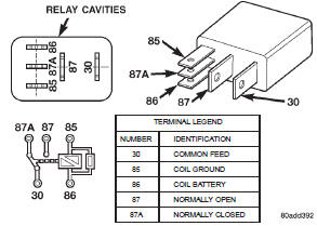
Fig. 11 Type-2 Relay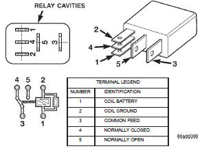
Fig. 12 Type-3 RelayFuel gauge sending unit
Fuel injector test


Other materials:
Dual function high pressure switch
(4.0 L). Evaporator coil. Fixed orifice tube
Dual function high pressure switch
(4.0 L)
DESCRIPTION
The Dual Function High Pressure Switch controls
both A/C clutch engagement/disengagement, and electric
cooling fan operations. The switch is located on
the discharge line near the compressor. The switch is
screwed onto a fitting that conta ...