Jeep Cherokee (XJ): Diagnosis and testing
A visual inspection for loose, disconnected or incorrectly
routed wires and hoses should be made. This
should be done before attempting to diagnose or service
the fuel injection system. A visual check will
help spot these faults and save unnecessary test and
diagnostic time. A thorough visual inspection will
include the following checks:
(1) Verify the three 32-way electrical connectors
are fully inserted into the connector of the Powertrain
Control Module (PCM) (Fig. 3).
1 - (3) 32-WAY CONNECTORS (2) Inspect battery cable connections. Be sure they
are clean and tight.
(3) Inspect fuel pump relay and air conditioning
compressor clutch relay (if equipped). Inspect ASD
relay connections. Inspect starter motor relay connections.
Inspect relays for signs of physical damage and
corrosion. The relays are located in Power Distribution
Center (PDC) (Fig. 4). Refer to label on PDC
cover for relay location.
(4) 2.5L Engine: Inspect ignition coil primary connection.
Verify coil secondary cable is firmly connected
to coil (Fig. 5).
(5) 4.0L Engine: Inspect ignition coil connection
(Fig. 6).
1 - POWER DISTRIBUTION CENTER (PDC)
1 - IGNITION COIL (6) 2.5L Engine: Verify that distributor cap is correctly
attached to distributor. Be sure that spark
plug cables are firmly connected to the distributor
cap and spark plugs are in their correct firing order.
Be sure that coil cable is firmly connected to distributor
cap and coil.
1 - REAR OF VALVE COVER (7) Connect vehicle to an oscilloscope and inspect
spark events for fouled or damaged spark plugs or
cables.
(8) Verify generator output wire, generator connector
and ground wire are firmly connected to generator.
(9) Inspect system body grounds for loose or dirty
connections. Refer to Group 8, Wiring for ground
locations.
(10) Verify crankcase ventilation (CCV) operation.
Refer to Group 25, Emission Control System for additional
information.
(11) Inspect fuel tube quick-connect fitting-to-fuel
rail connections.
(12) Verify hose connections to all ports of vacuum
fittings on intake manifold are tight and not leaking.
(13) Inspect accelerator cable, transmission throttle
cable (if equipped) and cruise control cable connections
(if equipped). Check their connections to
throttle arm of throttle body for any binding or
restrictions.
(14) If equipped with vacuum brake booster, verify
vacuum booster hose is firmly connected to fitting on
intake manifold. Also check connection to brake vacuum
booster.
(15) Inspect air cleaner inlet and air cleaner element
for dirt or restrictions.
(16) Inspect radiator grille area, radiator fins and
air conditioning condenser for restrictions.
(17) Verify intake manifold air temperature sensor
wire connector is firmly connected to harness connector
(Fig. 7) or (Fig. 8).
1 - ELECTRICAL CONNECTOR (18) Verify MAP sensor electrical connector is
firmly connected to MAP sensor (Fig. 8). Also verify
rubber L-shaped fitting from MAP sensor to throttle
body is firmly connected (Fig. 9).
(19) Verify fuel injector wire harness connectors
are firmly connected to injectors in correct order.
Each harness connector is numerically tagged with
injector number (INJ 1, INJ 2 etc.) of its corresponding
fuel injector and cylinder number.
(20) Verify harness connectors are firmly connected
to idle air control (IAC) motor and throttle
position sensor (TPS) (Fig. 8).
(21) Verify wire harness connector is firmly connected
to engine coolant temperature sensor (Fig.
10).
(22) Raise and support vehicle.
1 - MOUNTING BOLTS (4)
1 - THROTTLE BODY
1 - THERMOSTAT HOUSING (23) Verify that all oxygen sensor wire connectors
are firmly connected to sensors. Inspect sensors and
connectors for damage (Fig. 11), (Fig. 12), (Fig. 13) or
(Fig. 14).
1 - 1/1 O2S
1 - 1/1 O2S
1 - 1/1 O2S
1 - 1/2 O2S (24) Inspect for pinched or leaking fuel tubes.
Inspect for pinched, cracked or leaking fuel hoses.
(25) Inspect for exhaust system restrictions such
as pinched exhaust pipes, collapsed muffler or
plugged catalytic convertor.
(26) If equipped with automatic transmission, verify
electrical harness is firmly connected to park/neutral
switch. Refer to Automatic Transmission section
of Group 21.
(27) Verify that electrical harness connector is
firmly connected to the vehicle speed sensor (Fig. 15).
(28) 2.5L 4-Cylinder Engine Only: Verify good
electrical connection at power steering pressure
switch (Fig. 16). This switch is not used with 4.0L
engines.
(29) Verify good electrical connections at fuel pump
module connector at front of fuel tank (Fig. 17).
(30) Verify good EVAP canister vent line connection
at front of fuel tank (Fig. 17).
(31) Verify good fuel supply line connection at
front of fuel tank (Fig. 17).
(32) Inspect all fuel lines/hoses for cracks or leaks.
(33) Inspect transmission torque convertor housing
(automatic transmission) or clutch housing (manual
transmission) for damage to timing ring on drive
plate/flywheel.
(34) Verify battery cable and solenoid feed wire
connections to starter solenoid are tight and clean.
Inspect for chaffed wires or wires rubbing up against
other components.
1 - SENSOR ELECTRICAL CONNECTOR
1 - POWER STEERING PRESSURE SWITCH
1 - FUEL PUMP MODULE CONNECTOR The following description of operation and
tests apply only to the Automatic Shutdown
(ASD) and fuel pump relays. The terminals on the
bottom of each relay are numbered. Two different
types of relays may be used, (Fig. 18) or (Fig. 19).
OPERATION TESTING The following procedure applies to the ASD and
fuel pump relays.
(1) Remove relay from connector before testing.
(2) With the relay removed from the vehicle, use
an ohmmeter to check the resistance between terminals
85 and 86. The resistance should be between 75
65 ohms.
(3) Connect the ohmmeter between terminals 30
and 87A. The ohmmeter should show continuity
between terminals 30 and 87A.
(4) Connect the ohmmeter between terminals 87
and 30. The ohmmeter should not show continuity at
this time.
(5) Connect one end of a jumper wire (16 gauge or
smaller) to relay terminal 85. Connect the other end
of the jumper wire to the ground side of a 12 volt
power source.
(6) Connect one end of another jumper wire (16
gauge or smaller) to the power side of the 12 volt
power source. Do not attach the other end of the
jumper wire to the relay at this time.
WARNING: DO NOT ALLOW OHMMETER TO CONTACT
TERMINALS 85 OR 86 DURING THIS TEST.
(7) Attach the other end of the jumper wire to
relay terminal 86. This activates the relay. The ohmmeter
should now show continuity between relay terminals
87 and 30. The ohmmeter should not show
continuity between relay terminals 87A and 30.
(8) Disconnect jumper wires.
(9) Replace the relay if it did not pass the continuity
and resistance tests. If the relay passed the tests,
it operates properly. Check the remainder of the ASD
and fuel pump relay circuits. Refer to the Wiring
Diagrams. The following test procedure has been developed to
check throttle body calibrations for correct idle conditions.
The procedure should be used to diagnose the
throttle body for conditions that may cause idle problems.
This procedure should be used only after
normal diagnostic procedures have failed to
produce results that indicate a throttle body
related problem. Be sure to check for proper
operation of the idle air control motor before
performing this test.
A special fixed orifice tool (number 6714) (Fig. 20)
must be used for the following test. This tool has a
fixed internal diameter of 0.185".
(1) Start the engine and bring to operating temperature.
Be sure all accessories are off before performing
this test.
(2) Shut off engine and remove air duct at throttle
body.
(3) 2.5L 4-Cylinder Engine: Near front/top of
valve cover, disconnect CCV tube at fixed orifice fitting
(Fig. 21). Insert Special Tool 6714 into end of
disconnected CCV tube (insert either end of tool into
tube). Let tool and tube hang disconnected at side of
engine.
(4) 4.0L 6-Cylinder Engine: Disconnect CCV
tube (Fig. 22) at intake manifold fitting. Attach a
short piece of rubber hose to special tool 6714 (insert
rubber hose to either end of tool). Install rubber hose/
tool to intake manifold fitting. Let CCV tube hang
disconnected at side of engine.
1 - AIR INLET FITTING (5) Connect DRB scan tool to 16-way data link
connector. This connector is located at lower edge of
instrument panel near steering column. Refer to
appropriate Powertrain Diagnostic Procedures service
manual for DRB operation.
(6) Start engine and allow to warm up.
(7) Using the DRB scan tool, scroll through menus
as follows: select-Stand Alone DRB III, select the
year 2000 Diagnostics, select-Engine, select-System
Test, select-Minimum Air Flow.
(8) The DRB scan tool will count down to stabilize
idle rpm and display minimum air flow idle rpm. The
idle rpm should be between 500 and 900 rpm. If idle
speed is outside these specifications, replace throttle
body. Refer to Throttle Body Removal/Installation.
(9) Disconnect DRB scan tool from vehicle.
(10) Remove orifice tool and connect CCV tube to
engine.
(11) Install air duct to throttle body.
1 - AIR INLET FITTINGVisual inspection
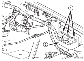
Fig. 3 Powertrain Control Module (PCM)
2 - PCM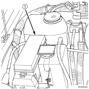
Fig. 4 Power Distribution Center (PDC)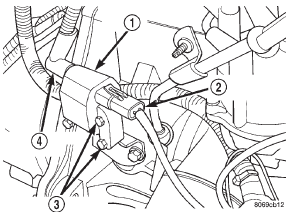
Fig. 5 Ignition Coil-2.5L Engine
2 - ELECTRICAL CONNECTOR
3 - MOUNTING BOLTS
4 - SECONDARY CABLE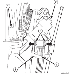
Fig. 6 Ignition Coil-4.0L Engine
2 - COIL RAIL
3 - SLIDE TAB
4 - RELEASE LOCK
5 - COIL CONNECTOR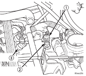
Fig. 7 Intake Manifold Air Temp. Sensor Location- 2.5L Engine
2 - INTAKE MANIFOLD TEMPERATURE SENSOR
3 - FUEL INJECTOR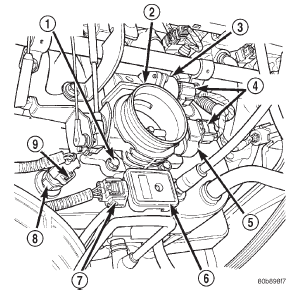
Fig. 8 Sensor Locations-4.0L Engine
2 - THROTTLE BODY
3 - IAC MOTOR
4 - ELEC. CONN.
5 - TPS
6 - MAP SENSOR
7 - ELEC. CONN.
8 - IAT SENSOR
9 - ELEC. CONN.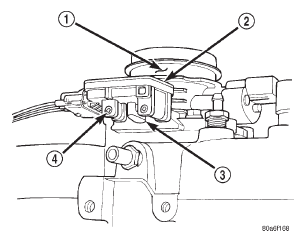
Fig. 9 Rubber L-Shaped Fitting-MAP Sensor-to-Throttle Body
2 - MAP SENSOR
3 - RUBBER FITTING
4 - MOUNTING SCREWS (2)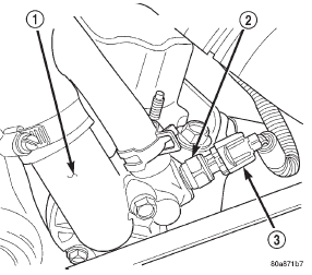
Fig. 10 Engine Coolant Temperature Sensor-Typical
2 - ENGINE COOLANT TEMPERATURE SENSOR
3 - ELECTRICAL CONNECTOR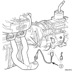
Fig. 11 Front Oxygen Sensor-4.0L-Federal Emissions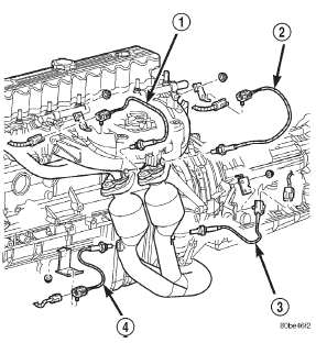
Fig. 12 Oxygen Sensors-4.0L-California Emissions
2 - 2/1 O2S
3 - 2/2 O2S
4 - 1/2 O2S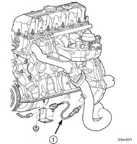
Fig. 13 Front Oxygen Sensor-2.5L-Federal Emissions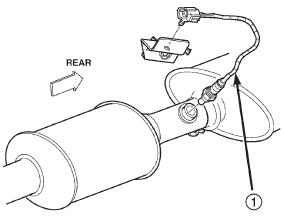
Fig. 14 Rear Oxygen Sensor-2.5L/4.0L-Federal Emissions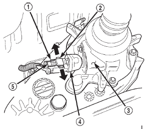
Fig. 15 Vehicle Speed Sensor-Typical-4WD Shown
2 - SLIDE TAB
3 - 4WD TRANSFER CASE EXTENSION
4 - VEHICLE SPEED SENSOR
5 - RELEASE LOCK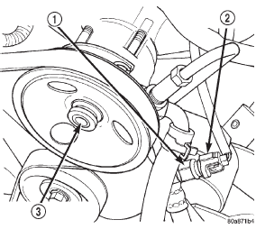
Fig. 16 Power Steering Pressure Switch-2.5L Engine
2 - ELECTRICAL CONNECTOR
3 - POWER STEERING PUMP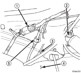
Fig. 17 Fuel Tank Connections at Front of Fuel Tank
2 - LEFT-REAR SHOCK ABSORBER
3 - EVAP CANISTER VENT LINE CONNECTION
4 - FRONT OF FUEL TANK
5 - FUEL SUPPLY LINE CONNECTIONASD and fuel pump relays
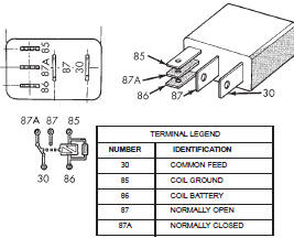
Fig. 18 ASD and Fuel Pump Relay Terminals-Type 1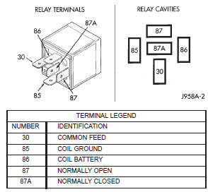
Fig. 19 ASD and Fuel Pump Relay Terminals-Type 2
Throttle body minimum air flow
check procedure
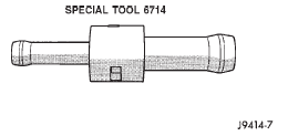
Fig. 20 6714 Fixed Orifice Tool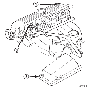
Fig. 21 Install Orifice Tool 2.5L 4-Cylinder Engine
2 - AIR FILTER COVER
3 - FIXED ORIFICE FITTING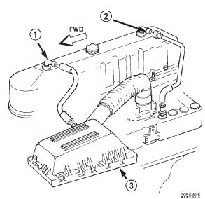
Fig. 22 Install Orifice Tool 4.0L 6-Cylinder Engine
2 - FIXED ORIFICE FITTING
3 - AIR FILTER COVER


Other materials:
Description and operation
Sentry key immobilizer module
The Sentry Key Immobilizer Module (SKIM) contains
a Radio Frequency (RF) transceiver and a central
processing unit, which includes the Sentry Key
Immobilizer System (SKIS) program logic. The SKIS
programming enables the SKIM to program and
retain in memory the code ...