Jeep Cherokee (XJ): Diagnosis and testing. Removal and installation. Disassembly and assembly
A low transmission lubricant level is generally the
result of a leak, inadequate lubricant fill, or an incorrect
lubricant level check.
Leaks can occur at the mating surfaces of the
housings, or from the front/rear seals. A suspected
leak could also be the result of an overfill condition.
Leaks at component mating surfaces will probably
be the result of inadequate sealer, gaps in the sealer,
incorrect bolt tightening, or use of a non-recommended
sealer.
A leak at the front of the transmission will be from
either a loose or damaged, front bearing retainer or
retainer seal. Lubricant may also drip from the
transmission clutch housing after extended operation.
If the leak is severe, it will contaminate the
clutch disc causing slip, grab and chatter.
Transmissions filled from air or electrically powered
lubricant containers can be under filled. Always
check the lubricant level after filling to avoid an
under fill condition.
A correct lubricant level check can only be made
when the vehicle is level; use a drive-on hoist to
ensure this. Also allow the lubricant to settle for a
minute or so before checking. These recommendations
will ensure an accurate check and avoid an
under-or-overfill condition. Hard shifting is usually caused by a low lubricant
level, improper or contaminated lubricants, transmission
component damage, clutch linkage malfunction,
or by a damaged clutch pressure plate or disc.
Substantial lubricant leaks can result in gear, shift
component, synchro and bearing damage. If a leak
goes undetected for an extended period, the first indications
of a problem are usually hard shifting and
noise.
Incorrect or contaminated lubricants can also contribute
to hard shifting. The consequence of using
non-recommended lubricants is noise, excessive
wear, internal bind and hard shifting.
Improper clutch release is a frequent cause of hard
shifting. Incorrect adjustment or a worn, damaged
pressure plate or disc can cause incorrect release. If
the clutch problem is advanced, gear clash during
shifts can result.
Worn or damaged synchro rings can cause gear
clash when shifting into any forward gear. In some
new or rebuilt transmissions, new synchro rings may
tend to stick slightly causing stiff and/or noisy shifts.
In most cases, this condition will decline as the rings
wear in. Most manual transmissions make some noise during
normal operation. Rotating gears can generate a
mild whine that may only be audible at extreme
speeds.
Severe, obviously audible transmission noise is
generally the result of a lubricant problem. Insufficient,
improper, or contaminated lubricant can promote
rapid wear of gears, synchros, shift rails, forks
and bearings. The overheating caused by a lubricant
problem, can also lead to gear breakage. REMOVAL (1) Shift transmission into first or third gear.
(2) Remove the floor console and shift boot as necessary
to access the bottom of the shift lever at the
shift tower attachment. (3) Install nuts on two M6X1.0 bolts and thread
the bolts into the threaded holes at the base of the
shift lever.
(4) Tighten the nuts equally until the shift lever
loosens on the shift tower stub shaft.
(5) Remove the shift lever from the shift tower.
(6) Raise and support vehicle on suitable safety
stands.
(7) Support engine with adjustable jack stand.
Position wood block between jack and oil pan to
avoid damaging pan.
(8) Remove crossmember/skid plate.
(9) Disconnect necessary exhaust system components.
(10) Remove skid plate, if equipped.
(11) Remove slave cylinder (Fig. 4) from clutch
housing.
1 - CLUTCH SLAVE CYLINDER (12) Mark rear propeller shaft and rear axle yokes
for installation alignment (Fig. 5).
(13) Mark front propeller shaft, axle, and transfer
case yokes for installation alignment, if equipped.
(14) Remove propeller shaft(s).
(15) Unclip wire harnesses from transmission and
transfer case, if equipped.
(16) Disconnect transfer case vent hose, if
equipped.
(17) Disengage any wire connectors attached to
transmission or transfer case, if equipped, components.
(18) Support transfer case, if equipped, with transmission
jack.
(19) Secure transfer case, if equipped, to jack with
safety chains.
1 - REFERENCE MARKS (20) Disconnect transfer case shift linkage at
transfer case, if equipped.
(21) Remove nuts attaching transfer case to transmission,
if equipped.
(22) Remove transfer case, if equipped.
(23) Remove crankshaft position sensor (Fig. 6).
1 - ENGINE SPEED SENSOR CAUTION: It is important that the crankshaft position
sensor be removed prior to transmission
removal. The sensor can easily be damaged if left
in place during removal operations. (24) Support engine with adjustable jack stand.
Position wood block between jack and oil pan to
avoid damaging pan.
(25) Support transmission with transmission jack.
(26) Secure transmission to jack with safety
chains.
(27) Disconnect rear cushion and bracket from
transmission.
(28) Remove rear crossmember.
(29) Remove clutch housing-to-engine bolts.
(30) Pull transmission jack rearward until input
shaft clears clutch. Then slide transmission out from
under vehicle.
(31) Remove clutch release bearing, release fork,
and retainer clip.
(32) Remove clutch housing from transmission
(Fig. 7).
1 - HOUSING-TO-TRANSMISSION BOLTS (46 N·m/34 ft. lbs.) INSTALLATION (1) Install clutch housing (Fig. 7) on transmission.
Tighten housing bolts to 46 N·m (34 ft. lbs.) torque.
(2) Lubricate contact surfaces of release fork pivot
ball stud and release fork with high temp grease.
(3) Install release bearing, fork, and retainer clip.
(4) Position and secure transmission on transmission
jack.
(5) Lightly lubricate pilot bearing and transmission
input shaft splines with Mopart high temp
grease.
(6) Raise transmission and align transmission
input shaft and clutch disc splines. Then slide transmission
into place.
(7) Install and tighten clutch housing-to-engine
bolts to the appropriate torque: Be sure the housing
is properly seated on engine block before
tightening bolts. (8) Be sure transmission is in first or third gear.
(9) Install rear crossmember. Tighten crossmember-
to-frame bolts to 41 N·m (31 ft. lbs.) torque.
(10) Install fasteners to hold rear cushion and
bracket to transmission. Then tighten transmissionto-
rear support bolts/nuts to 54 N·m (40 ft. lbs.)
torque.
(11) Remove support stands from engine and
transmission.
(12) Install and connect crankshaft position sensor.
(13) Position transfer case on transmission jack, if
equipped.
(14) Secure transfer case to jack with safety
chains, if equipped.
(15) Raise transfer case, if equipped, and align
transfer case input shaft to the transmission output
shaft.
(16) Slide transfer case forward until case is
seated on transmission, if necessary.
(17) Install nuts to attach transfer case to transmission,
if equipped. Tighten transfer case-to-transmission
nuts to 35 N·m (26 ft. lbs.) torque.
(18) Connect transfer case shift linkage at transfer
case, if equipped.
(19) Connect transfer case vent hose, if equipped.
(20) Secure wire harnesses in clips/tie straps on
transmission and transfer case, if equipped.
(21) Engage wire connectors attached to all necessary
transmission or transfer case, if equipped, components.
(22) Install rear propeller shaft slip yoke to transmission
or transfer case, if equipped, output shaft.
(23) Align marks on rear propeller shaft and rear
axle yokes (Fig. 8).
(24) Install and tighten propeller shaft U-joint
clamp bolts to 19 N·m (170 in. lbs.) torque.
(25) Align marks on front propeller shaft, axle,
and transfer case yokes, if equipped.
(26) Install and tighten propeller shaft U-joint
clamp bolts to 19 N·m (170 in. lbs.) torque.
(27) Install slave cylinder in clutch housing.
1 - REFERENCE MARKS (28) Install skid plate, if equipped. Tighten bolts to
42 N·m (31 ft. lbs.) torque. Tighten stud nuts to 17
N·m (150 in. lbs.) torque.
(29) Fill transmission and transfer case, if
equipped, with recommended lubricants. Refer to the
Lubricant Recommendation sections of the appropriate
component for correct fluid.
(30) Lower vehicle.
(31) Install nuts on two M6X1.0 bolts and thread
the bolts into the threaded holes at the base of the
shift lever.
(32) Tighten the nuts equally until the shift lever
will slide over the shift tower stub shaft.
(33) Install the floor console and shift boot. REMOVAL (1) Shift transmission into Neutral.
(2) Unscrew and remove the shift lever extension
from the shift
(3) Remove any floor console components necessary
to access the transmission shift tower.
(4) Remove the bolts holding the shift tower to the
isolator plate and transmission gear case.
(5) Remove the shift tower (Fig. 9) from the transmission. INSTALLATION (1) Shift transmission into third gear.
(2) Clean the mating surfaces of shift tower and
transmission gear case with suitable wax and grease
remover.
(3) Install the shift tower onto the transmission
case. No sealant is necessary between the shift tower
and transmission case.
1 - SHIFT TOWER AND LEVER ASSEMBLY (4) Install the bolts to hold the shift tower to the
isolator plate and the transmission gear case.
Tighten the shift tower bolts to 8.5 N·m (6.3 ft. lbs.).
(5) Install the shift lever extension and any floor
console components previously removed. REMOVAL (1) Raise vehicle.
(2) Mark propeller shaft and axle yoke for alignment
reference.
(3) Disconnect and remove propeller shaft.
(4) Remove old seal with Seal Remover C-3985-B
(Fig. 10) from transmission housing. 1 - SPECIAL TOOL C-3985-B INSTALLATION (1) Place seal in position on transmission housing.
(2) Drive seal into transmission housing with Seal
Installer C-3972-A (Fig. 11). (3) Carefully guide propeller shaft slip yoke into
housing and onto output shaft splines.
(4) Align marks made at removal and connect propeller
shaft to rear axle pinion yoke.
1 - SPECIAL TOOL C-4171 REMOVAL (1) Remove housing yoke seal.
(2) Insert Remover 6957 into rear housing. Tighten
tool to bushing and remove bushing (Fig. 12).
1 - REMOVER 6957 INSTALLATION (1) Align bushing oil hole with oil slot in rear
housing.
(2) Tap bushing into place with Installer 6951 and
Handle C-4171.
(3) Install new oil seal in housing using Seal
Installer C-3972-A (Fig. 13).
1 - SPECIAL TOOL C-4171 TRANSMISSION DISASSEMBLY FRONT HOUSING (1) If necessary, temporarily reinstall shift lever
assembly. Shift transmission into Neutral.
(2) If lubricant was not drained out of transmission
during removal, remove drain plug and drain
lubricant into container at this time.
(3) Inspect drain plug magnet for debris.
(4) Remove backup light switch. Switch is located
on passenger side of rear housing (Fig. 14).
1 - BACKUP LIGHT SWITCH (5) If necessary, remove shift tower bolts and
remove tower and lever assembly (Fig. 15).
(6) Remove shift shaft lock bolt (Fig. 16). Bolt is
located at top of front housing just forward of shift
tower. Bolt is a shoulder bolt that secures the shift
shaft bushing and lever.
(7) Use Remover 8117 and suitable slide hammer
to remove shift shaft detent plug.
1 - SHIFT TOWER AND LEVER ASSEMBLY
1 - SHIFT SHAFT LOCK BOLT (8) Remove shift shaft detent plunger and spring
(Fig. 17). Use pencil magnet to remove spring then
plunger, if necessary.
(9) Remove bolts attaching input shaft bearing
retainer to front housing (Fig. 18).
1 - FRONT HOUSING
1 - INPUT SHAFT BEARING RETAINER (10) Remove input shaft bearing retainer. Use pry
tool to carefully lift retainer and break sealer bead
(Fig. 19).
1 - PRYTOOL (11) Remove bearing retainer from input shaft
(Fig. 20).
1 - SHAFT BEARING (12) Remove snap ring that secures input shaft in
front bearing (Fig. 21).
(13) Remove bolts that attach front housing to rear
housing (Fig. 22). Three bolts at extreme rear of
housing are actually for the output shaft bearing
retainer. It is not necessary to remove all three bolts
at this time. Leave at least one bolt in place until
geartrain is ready to be removed from case.
1 - INPUT SHAFT SNAP RING
1 - RETAINER BOLTS (14) Separate front housing from rear housing
(Fig. 23). Use plastic mallet to tap front housing off
alignment dowels.
1 - FRONT HOUSING
1 - INPUT SHAFT BEARING (16) Note position of input shaft, shift shaft and
forks, and geartrain components in housing (Fig. 25).
1 - SHIFT SHAFT SHIFT SHAFT, SHIFT FORKS AND REVERSE IDLER SEGMENT (1) Unseat the roll pin that secures the shift
socket tot he shift shaft with Special Tool 6858 as follows:
(a) Position Tool 6858 on the shift shaft. Center
the tool over the roll pin and verify that the tool
legs are firmly seated on the shift socket (Fig. 26).
(b) Tilt the socket toward the side of the case.
This positions the roll pin at a slight angle to avoid
trapping the pin between the gear teeth.
(c) Tighten the tool punch to press the roll pin
downward and out of the shift socket (Fig. 26). The
roll pin does not have to be completely removed
from the shift socket. The roll pin must only be
clear of the shift shaft. Be careful not to push the
pin into the geartrain.
(2) Using a hammer and suitable punch, drive out
roll pin that secures shift bushing and lever to shift
shaft (Fig. 27).
NOTE: Be sure to use the proper size punch to
avoid bending the shift shaft.
1 - SPECIAL TOOL
6858
1 - PIN PUNCH (3) Pull shift shaft straight out of rear housing,
shift socket, fifth-reverse fork, and 1-2 fork (Fig. 28).
(4) Remove shift socket from rear housing (Fig.
29).
(5) Remove lever and bushing (Fig. 30).
(6) Remove 3-4 fork. Rotate 3-4 fork around synchro
sleeve until fork clears shift arms on 1-2 and
fifth-reverse forks. Then remove 3-4 fork (Fig. 31).
(7) Remove the reverse idler shaft support bolt
(front bolt) (Fig. 32).
1 - SHIFT SHAFT
1 - SHAFT BORE
1 - SHAFT LEVER AND BUSHING
1 - 3-4 FORK (8) Loosen rear reverse idler shaft bolt (rear bolt)
(Fig. 32).
1 - SUPPORT BOLT (9) Remove reverse idler shaft support segment by
sliding it straight out of housing.
(10) Support geartrain and rear housing on Assembly
Fixture Tool 6747 as follows:
(a) Adjust height of reverse idler pedestal rod
until the reverse idle shaft bottoms in Cup 8115.
(b) Position Adapters 6747-1A and 6747-2A on
Assembly Fixture 6747.
(c) Slide fixture tool onto input shaft, countershaft
and idler gear (Fig. 33).
(d) Stand geartrain and rear housing upright on
fixture (Fig. 34). Have helper hold fixture tool in
place while housing and geartrain is being rotated
into upright position.
1 - SPECIAL TOOL 6747
1 - INPUT SHAFT (11) Remove rear bolt holding reverse idler shaft
in housing. REAR HOUSING REMOVAL-2WD (1) On 2-wheel drive transmission, remove three
bolts that attach output shaft bearing retainer to
rear case (Fig. 35). Bolts are rear of shift tower opening.
1 - OUTPUT SHAFT BEARING RETAINER BOLTS (THIRD BOLT
IS AT OPPOSITE SIDE OF CASE) (2) Unseat output shaft bearing from bearing bore
in rear housing. Use plastic or rawhide mallet to tap
rear housing upward and off output shaft bearing as
shown (Fig. 36).
(3) Lift rear housing up and off geartrain (Fig. 37).
(4) Remove countershaft rear bearing from countershaft
(Fig. 38).
(5) Examine condition of bearing bore and idler
shaft notch in rear housing. Replace housing if any of
these components are damaged.
1 - REAR HOUSING REAR ADAPTER HOUSING REMOVAL-4WD (1) Locate dimples in face of rear seal (Fig. 39).
Use a suitable slide hammer mounted screw to
remove seal by inserting screw into seal at dimple
locations (Fig. 40).
1 - REAR HOUSING
1 - COUNTERSHAFT REAR BEARING
1 - LOCATION OF DIMPLES
1 - SLIDE HAMMER (2) Remove rear bearing snap ring from output
shaft with heavy duty snap ring pliers (Fig. 41).
(3) Lift rear adapter housing upward and off
geartrain (Fig. 42).
1 - HEAVY DUTY SNAP RING PLIERS
1 - REAR ADAPTER HOUSING (4) Remove bearing retainer bolts and remove rear
bearing retainer and rear bearing (Fig. 43). Use hammer
handle to push or tap bearing out of housing if
needed.
(5) Examine condition of bearing bore, countershaft
rear bearing race and idler shaft notch in rear
housing. Replace housing if race, bore or notch are
worn or damaged.
1 - BEARING RETAINER GEARTRAIN DISASSEMBLY FROM FIXTURE (1) Remove reverse idler gear assembly from
assembly fixture cup.
(2) Remove 1-2 and fifth-reverse forks from synchro
sleeves.
(3) Slide countershaft out of fixture tool.
(4) Remove output shaft bearing retainer from
rear surface of fifth gear (retainer will drop onto gear
after bolts are removed).
(5) Lift and remove output shaft and gears off
input shaft.
(6) Lift and remove input shaft, pilot bearing and
fourth gear synchro ring from assembly fixture tool. OUTPUT SHAFT NOTE: The synchronizer hubs and sleeves are different
and must not be intermixed. It is recommended
that each synchronizer unit be removed as
an assembly to avoid intermixing parts. It is also
recommended that each synchro hub and sleeve be
marked with a scriber or paint for correct assembly
reference.
(1) Remove snap ring that secures 3-4 synchro hub
on output shaft.
(2) Remove 3-4 synchro assembly, third gear synchro
ring, and third gear with shop press and
Remover Tool 1130. Position Tool 1130 between second
and third gears.
(3) Remove third gear needle bearing (Fig. 44).
1 - THIRD GEAR NEEDLE BEARING (4) Remove retaining ring that secures two-piece
thrust washer on shaft (Fig. 45). Use small pry tool
to remove retaining ring.
1 - PRYTOOL (5) Remove two-piece thrust washer (Fig. 46). Note
position of washer locating lugs in shaft notches for
installation reference.
1 - SECOND GEAR
1 - SECOND GEAR (7) Remove second gear synchro ring, synchro friction
cone, and synchro cone (Fig. 48).
(8) Remove interm ring.
(9) Remove 1-2 synchro hub snap ring.
(10) Remove 1-2 synchro hub and sleeve and first
gear from output shaft with shop press and Remover
Tool 1130 (Fig. 49). Position Tool 1130 between first
and reverse gears.
1 - 1-2 SYNCHRO HUB AND SLEEVE
1 - 1-2 SYNCHRO HUB AND SLEEVE (11) Remove first gear needle bearing (Fig. 50).
(12) Remove output shaft bearing snap ring (Fig.
51).
(13) On 2-wheel drive models, remove output shaft
bearing.
(14) Remove fifth gear (Fig. 52).
1 - FIRST GEAR NEEDLE BEARING
1 - OUTPUT SHAFT BEARING
1 - FIFTH GEAR AND SYNCHRO RING (15) Remove fifth gear needle bearing. Spread
bearing apart just enough to clear shoulder on output
shaft (Fig. 53).
1 - FIFTH GEAR NEEDLE BEARING (SPREAD BEARING TO
CLEAR SHOULDER ON SHAFT) (16) Remove fifth-reverse synchro hub snap ring
(Fig. 54).
1 - FIFTH-REVERSE SYNCHRO HUB AND SLEEVE (17) Remove fifth-reverse synchro hub and sleeve
with shop press (Fig. 55).
1 - PRESS (18) Remove reverse gear and needle bearing (Fig.
56).
1 - REVERSE GEAR AND NEEDLE BEARING
1 - SNAP RING REVERSE IDLER DISASSEMBLY (1) Remove idler gear snap rings (Fig. 57).
(2) Remove thrust washer, wave washer, thrust
plate and idler gear from shaft.
(3) Remove idler gear needle bearing from shaft. ASSEMBLY Gaskets are not used in the NV3550 transmission.
Sealers are used at all case joints. Recommended
sealers are Mopart Gasket Maker for all case joints
and Mopart silicone sealer, or equivalent, for the
input shaft bearing retainer. Apply these products as
indicated in the assembly procedures.
NOTE: It is very important that the transmission
shift components be in Neutral position during
assembly. This is necessary to prevent damaging
synchro and shift components when the housings
are installed.
The 3-4, 1-2 and fifth-reverse synchro hub snap
rings can be fitted selectively. New snap rings are
available in 0.05 mm (0.0019 in.) thickness increments.
Use the thickest snap ring that will fit in
each snap ring groove. SYNCHRONIZER The easiest method of assembling each synchro is
to install the springs, struts and detent balls one at a
time as follows:
(1) Slide the sleeve part way onto the hub. Leave
enough room to install the spring in the hub and the
strut in the hub groove.
(2) Install the first spring in the hub. Then install
a strut over the spring. Be sure the spring is seated
in the spring bore in the strut.
(3) Slide the sleeve onto the hub just far enough to
hold the first strut and spring in place.
(4) Place the detent ball in the top of the strut.
Then carefully work the sleeve over the ball to hold
it in place. A small flat blade screwdriver can be used
to press the ball into place while moving the sleeve
over it.
(5) Repeat the procedure for the remaining
springs, struts and balls. Tape, or a rubber band can
be used to temporarily secure each strut and ball as
they are installed.
(6) Verify synchro assembly. Be sure the three
springs, struts and detent balls are all in place (Fig.
58).
1 - SLEEVE OUTPUT SHAFT (1) Lubricate shaft, gears and bearings with recommended
lubricant during assembly. Petroleum
jelly can be used to hold parts in place.
(2) Check bearing surfaces of output shaft for
nicks or scratches. Smooth surfaces with 320/400 grit
emery cloth if necessary. Apply oil to emery cloth and
shaft surface before polishing.
(3) Inspect and replace any synchro ring that
exhibits wear or damage. Completely immerse each
synchro ring in lubricant before installation.
(4) Lubricate and install reverse gear needle bearing
on shaft (Fig. 59). Slide bearing up against shoulder
on output shaft.
(5) Install reverse gear over needle bearing (Fig.
60).
(6) Install solid brass synchro ring on reverse gear
(Fig. 61).
1 - REVERSE GEAR BEARING
1 - REVERSE GEAR
1 - REVERSE GEAR
2 - SYNCHRO RING (SOLID BRASS) (7) Assemble fifth-reverse synchro hub, sleeve,
struts, springs and detent balls, if not previously
done.
CAUTION: The fifth-reverse synchro hub and
sleeve can be installed backwards if care is not
exercised. One side of the hub has shoulders
around the hub bore. Make sure this side of the hub
is facing the front of the shaft. In addition, one side
of the sleeve is tapered. Be sure the sleeve is
installed so the tapered side will be facing the front
of the shaft.
(8) Start fifth-reverse synchro assembly on output
shaft splines by hand. Then seat synchro onto shaft
with shop press and Remover 6310-1 (Fig. 62).
1 - SPACER (9) Install new fifth-reverse hub snap ring (Fig.
63) as follows:
(a) Snap rings are available in thicknesses from
2.00 mm to 2.20 mm (0.078 to 0.086 in.).
(b) Install thickest snap ring that will fit in
shaft groove.
(c) Verify that snap ring is completely seated in
groove before proceeding.
1 - FIFTH-REVERSE SYNCHRO ASSEMBLY
1 - FIFTH-SPEED SYNCHRO RING (11) Install fifth gear bearing. Spread bearing only
enough to clear shoulder on output shaft (Fig. 65). Be
sure bearing is properly seated after installation.
(12) Install fifth gear on shaft and onto bearing
(Fig. 66).
1 - SHAFT SHOULDER
1 - FIFTH GEAR (13) Invert output shaft and set the shaft in
Remover 6310-1 so that fifth gear is seated on the
tool (Fig. 67).
(14) Install first gear bearing on output shaft (Fig.
67). Be sure bearing is seated on shaft shoulder and
is properly joined.
(15) Install first gear on shaft and over bearing
(Fig. 68). Make sure bearing synchro cone is facing
up as shown.
1 - FIRST GEAR BEARING
1 - FIRST GEAR (16) Install first gear synchro ring (Fig. 69).
1 - FIRST GEAR SYNCHRO RING (17) Assemble 1-2 synchro hub sleeve, springs,
struts and detent balls.
CAUTION: The 1-2 synchro hub and sleeve can be
installed backwards if care is not exercised. One
side of the synchro sleeve is marked First Gear
Side. Be sure this side of the sleeve will face first
gear after installation.
(18) Start 1-2 synchro assembly on shaft by hand
(Fig. 70). Be sure synchro sleeve is properly positioned.
Side marked first side must be facing first gear.
1 - 1-2 SYNCHRO ASSEMBLY (19) Press 1-2 synchro onto output shaft using
suitable size pipe tool and shop press (Fig. 71).
CAUTION: Take time to align the synchro ring and
sleeve as hub the is being pressed onto the shaft.
The synchro ring can be cracked if it becomes misaligned.
1 - SUITABLE SIZE PIPE TOOL (20) Install interm ring.
(21) Install new 1-2 synchro hub snap ring (Fig.
72) as follows:
(a) Snap rings are available in thicknesses from
1.80 mm to 2.00 mm (0.070 to 0.078 in.).
(b) Install thickest snap ring that will fit in
shaft groove.
(c) Verify that snap ring is completely seated in
groove before proceeding.
(22) Install second gear synchro ring in 1-2 synchro
hub and sleeve (Fig. 73). Be sure synchro ring is
properly seated in sleeve.
1 - 1-2 SYNCHRO (23) Install synchro friction cone and synchro cone
in synchro ring.
1 - SECOND GEAR SYNCHRO RING (24) Install second gear needle bearing on shaft
(Fig. 74).
1 - SECOND GEAR BEARING (25) Install second gear onto shaft and bearing
(Fig. 75). Make sure that second gear is fully seated
on synchro components.
1 - SPECIAL TOOL
6310-1 (26) Install two-piece thrust washer (Fig. 76). Be
sure washer halves are seated in shaft groove and
that washer lugs are seated in shaft lug bores. Also,
ensure that the i.d. grooves and markings noted during
removal are facing the correct direction.
1 - WASHER GROOVE IN SHAFT (27) Start retaining ring around two-piece thrust
washer (Fig. 77). Make sure that the locating dimple
is between the thrust washer halves.
(28) Seat thrust washer retaining ring with plastic
mallet (Fig. 78).
1 - THRUST WASHER RETAINING RING
1 - PLASTIC MALLET (29) Install third gear needle bearing on shaft (Fig.
79).
1 - THIRD GEAR BEARING (30) Install third gear on shaft and bearing (Fig.
80).
1 - THIRD GEAR (31) Install third speed synchro ring on third gear
(Fig. 81).
(32) Assemble 3-4 synchro hub, sleeve, springs,
struts and detent balls.
CAUTION: The 3-4 synchro hub and sleeve can be
installed backwards if care is not exercised. One
side of the sleeve has grooves in it. Be sure this
side of sleeve is also facing the front of the shaft.
1 - THIRD SPEED SYNCHRO RING (33) Start 3-4 synchro hub on output shaft splines
by hand (Fig. 82).
1 - GROOVED SIDE OF SLEEVE (TO FRONT) (34) Press 3-4 synchro assembly onto output shaft
with shop press and suitable size pipe tool (Fig. 83).
Make sure that the tool presses on hub as close to
output shaft as possible but does not contact the
shaft splines.
1 - PRESS RAM (35) Install 3-4 synchro hub snap ring (Fig. 84) as
follows:
(a) Snap rings are available in thicknesses from
2.00 mm to 2.30 mm (0.078 to 0.090 in.).
(b) Install thickest snap ring that will fit in
shaft groove. Use heavy duty snap ring pliers to
install new ring.
(c) Verify that snap ring is completely seated in
groove before proceeding.
1 - 3-4 SYNCHRO HUB SNAP RING (36) Install output shaft bearing.
(37) Install output shaft bearing snap ring (Fig.
85). Use heavy duty snap ring pliers and spread snap
ring only enough to install it. Be sure snap ring is
completely seated in shaft groove before proceeding.
1 - BEARING SNAP RING (38) Verify correct position of synchro sleeves
before proceeding with assembly operations (Fig. 86).
Grooved side of 3-4 sleeve should be facing forward.
First gear side of 1-2 sleeve should be facing first
gear. Tapered side of fifth-reverse sleeve should be
facing forward. REVERSE IDLER ASSEMBLY (1) Lubricate idler components with gear lube.
(2) Slide idler gear bearing on shaft (Fig. 87).
Bearing fits either way on shaft.
(3) Slide gear onto shaft. Side of gear with recess
goes to rear (Fig. 87).
(4) Place first lock ball in dimple at rear end of
idler shaft (Fig. 87). Petroleum jelly can be used to
hold ball in place if desired.
(5) Slide thrust rear thrust washer onto shaft and
over lock ball (Fig. 88).
(6) Install snap ring in groove at rear of shaft (Fig.
88).
(7) Install lock ball in dimple at front of shaft.
Hold ball in place with petroleum jelly if desired.
1 - DOUBLE GROOVE FORWARD
1 - IDLER GEAR (8) Install front thrust washer on shaft and slide
washer up against gear and over lock ball (Fig. 89).
1 - LOCK BALL (9) Install wave washer, flat washer and remaining
snap ring on idler shaft (Fig. 89). Be sure snap
ring is fully seated.
1 - REAR OF SHAFT SHIFT SHAFT AND DETENT PLUNGER BUSHINGS/BEARINGS (1) Inspect shift shaft bushing and bearing for
damage.
(2) If necessary, the shift shaft bushing can be
replaced as follows:
(a) Locate a bolt that will thread into the bushing
without great effort.
(b) Thread the bolt into the bushing, allowing
the bolt to make its own threads in the bushing.
(c) Attach a slide hammer or suitable puller to
the bolt and remove bushing.
(d) Use the short end of Installer 8119 to install
the new bushing.
(e) The bushing is correctly installed if the bushing
is flush with the transmission case.
(3) If necessary, the shift shaft bearing can be
replaced as follows:
(a) Locate a bolt that will thread into the bearing
without great effort.
(b) Thread the bolt into the bearing as much as
possible.
(c) Attach a slide hammer or suitable puller to
the bolt and remove the bearing.
(d) Use the short end of Installer 8119 to install
the new bearing.
(e) The bearing is correctly installed if the bearing
is flush with the transmission case.
(4) Inspect detent plunger bushings for damage.
NOTE: The detent plunger bushings are installed to
a specific depth. The space between the two bushings
when correctly installed contain an oil feed
hole. Do not attempt to install the bushings with
anything other than the specified tool or this oil
hole may become restricted.
(5) If necessary, the detent plunger bushings can
be replaced as follows:
(a) Using the long end of Installer 8119, drive
the detent bushings through the outer case and
into the shift shaft bore.
(b) Remove the bushings from the shift shaft
bore.
(c) Install a new detent plunger bushing on the
long end of Installer 8118.
(d) Start the bushing in the detent plunger bore
in the case.
(e) Drive the bushing into the bore until the tool
contacts the transmission case.
(f) Install a new detent plunger bushing on the
short end of Installer 8118.
(g) Start the bushing in the detent plunger bore
in the case.
(h) Drive the bushing into the bore until the tool
contacts the transmission case. GEARTRAIN ASSEMBLY (1) Install Adapter 6747-1A on input shaft hub of
fixture tool (Fig. 90). Then install Adapter 6747-2A
on front bearing hub of countershaft. Adapter
6747-2A has a raised shoulder on one side. Be sure
the shoulder is seated against the countershaft.
(2) Install input shaft in fixture tool. Make sure
Adapter Tool 6747-1A is positioned under shaft as
shown (Fig. 91).
(3) Install pilot bearing in input shaft (Fig. 91).
NOTE: There is a correct and an incorrect way to
install the pilot bearing into the input shaft. The
side of the pilot bearing with the small diameter
goes toward the input shaft.
1 - SPECIAL TOOL 6747-2A (INSTALL ON COUNTERSHAFT
FRONT HUB)
1 - PILOT BEARING (4) Install fourth gear synchro ring on input shaft
(Fig. 92).
1 - FOURTH GEAR SYNCHRO RING (5) Adjust height of idler gear pedestal on assembly
fixture (Fig. 93). Start with a basic height of 18.4
cm (7-1/4 in.). Final adjustment can be made after
gear is positioned on pedestal.
1 - REVERSE IDLER PEDESTAL (6) Install assembled output shaft and geartrain in
input shaft (Fig. 94). Carefully rotate output shaft
until the 3-4 synchro ring seats in synchro hub and
sleeve.
1 - OUTPUT SHAFT AND GEARTRAIN (7) Install Adapter 6747-2A on front bearing hub of
countershaft, if not previously done. The adapter has
a shoulder on one side. The shoulder goes toward the
countershaft.
(8) Slide countershaft (and adapter) into fixture
slot. Verify that countershaft and output shaft gears
are fully meshed with the mainshaft gears before
proceeding (Fig. 95).
(9) Check alignment of countershaft and output
shaft gear teeth. Note that gears may not align perfectly.
A difference in height of 1.57 to 3.18 mm (1/16
to 1/8 in.) will probably exist. This difference will not
interfere with assembly. However, if the difference is
greater than this, the countershaft adapter tool is
probably upside down. Remove countershaft, reverse
adapter tool, reinstall countershaft and check alignment
again.
1 - OUTPUT SHAFT AND GEARTRAIN (10) Position reverse idler in support cup of assembly
fixture (Fig. 96). Be sure idler gear is properly
meshed and aligned with shaft gear teeth and that
bolt holes are facing out and not toward geartrain.
Adjust pedestal up or down if necessary. Also be sure
that short end of idler shaft is facing up as shown.
1 - OUTPUT SHAFT AND GEARTRAIN (11) On 2-wheel drive transmission, thread one
Pilot Stud 8120 in center or passenger side hole of
output shaft bearing retainer. Then position retainer
on fifth gear as shown (Fig. 97).
(12) Assemble 1-2 and fifth reverse-shift forks (Fig.
98). Arm of fifth-reverse fork goes through slot in 1-2
fork.
1 - SPECIAL TOOL
8120
1 - INSERT ARM THROUGH 1-2 FORK (13) Install assembled shift forks in synchro
sleeves (Fig. 99). Be sure forks are properly seated in
sleeves.
1 - SYNCHRO SLEEVES REAR HOUSING-2WD (1) Drive adapter housing alignment dowels back
into housing until dowels are flush with mounting
surface (Fig. 100).
1 - HOUSING ALIGNMENT DOWELS (2) Apply liberal quantity of petroleum jelly to
countershaft rear bearing and bearing race.
(3) Install countershaft rear bearing in bearing
race (Fig. 101).
CAUTION: The countershaft bearings can be
installed backwards if care is not exercised. Be
sure the large diameter side of the roller retainer
faces the countershaft and the small diameter side
faces the race and housing (Fig. 102).
(4) Apply extra petroleum jelly to hold countershaft
rear bearing in place when housing is installed.
(5) Apply light coat of petroleum jelly to shift shaft
bushing/bearing in rear housing (Fig. 102).
(6) Reach into countershaft rear bearing with finger,
and push each bearing roller outward against
race. Then apply extra petroleum jelly to hold rollers
in place. This avoids having rollers becoming displaced
during housing installation. This will result in
misalignment between bearing and countershaft
bearing hub.
1 - COUNTERSHAFT REAR BEARING
1 - SHIFT SHAFT BUSHING/BEARING (7) Install rear housing onto geartrain (Fig. 103).
Be sure bearing retainer pilot stud is in correct bolt
hole in housing. Also be sure countershaft and output
shaft bearings are aligned in housing and on countershaft.
It may be necessary to lift upward on countershaft
slightly to ensure that the countershaft rear
bearing engages to the countershaft before the rear
output shaft bearing engages the housing.
Description and operationDiagnosis and testing
Low lubricant level
Hard shifting
Transmission noise
Removal and installation
Transmission
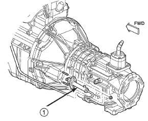
Fig. 4 Slave Cylinder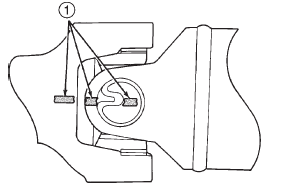
Fig. 5 Marking Propeller Shaft And Axle Yokes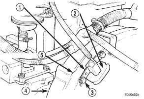
Fig. 6 Crankshaft Position Sensor -2.5 and 4.0L Engine
2 - GROMMET
3 - MOUNTING BOLT(S)
4 - LEFT REAR OF ENGINE
5 - TRANSMISSION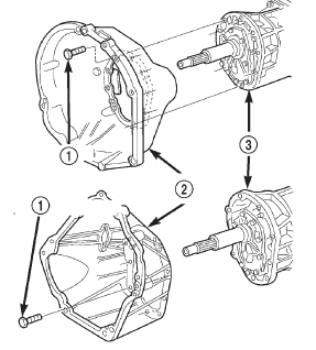
Fig. 7 Clutch Hou
2 - CLUTCH HOUSING
3 - TRANSMISSION
Fig. 8 Align Propeller Shaft And Rear Axle Yokes Alignment MarksShift tower
Fig. 9 Remove Shift Tower
2 - SHIFT SOCKET
3 - SEALYoke seal-2WD
2 - SEAL
Fig. 11 Installing Transmission Housing Yoke Seal
2 - SPECIAL TOOL C-3972-ARear housing yoke bushing
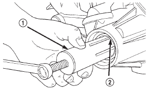
Fig. 12 Bushing Removal-Typical
2 - EXTENSION HOUSING BUSHING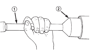
Fig. 13 Rear Housing Seal Installation
2 - SPECIAL TOOL C-3972-ADisassembly and assembly
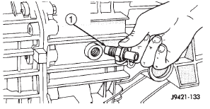
Fig. 14 Backup Light Switch Location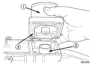
Fig. 15 Shift Tower Removal
2 - SHIFT SOCKET
3 - SEAL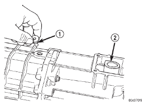
Fig. 16 Shift Shaft Lock Bolt Removal
2 - SHAFT SOCKET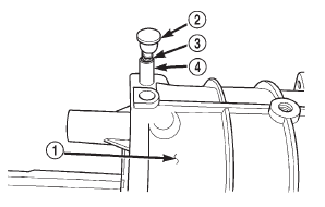
Fig. 17 Detent Plunger And Spring Removal
2 - PLUG
3 - SPRING
4 - PLUNGER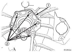
Fig. 18 Input Shaft Bearing Retainer Bolt Removal-Typical
2 - RETAINER BOLTS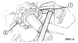
Fig. 19 Loosening Bearing Retainer Sealer Bead-Typical
2 - INPUT SHAFT BEARING RETAINER
Fig. 20 Input Shaft Bearing Retainer Removal-Typical
2 - BEARING RETAINER
3 - INPUT SHAFT
Fig. 21 Input Shaft Snap Ring Removal-Typical
2 - OIL FEED
Fig. 22 Housing And Bearing Retainer Bolt Locations
2 - HOUSING BOLTS
3 - RETAINER BOLT
4 - HOUSING BOLT LOCATIONS
Fig. 23 Front Housing Removal
2 - REAR HOUSING
3 - DOWELS (2)
4 - PLASTIC MALLET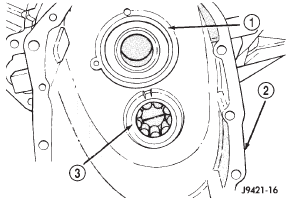
Fig. 24 Input Shaft Bearing and Countershaft Front Bearing Race Location
2 - FRONT HOUSING
3 - COUNTERSHAFT FRONT BEARING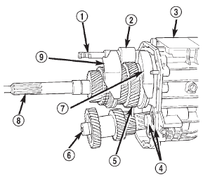
Fig. 25 Geartrain And Shift Component Identification
2 - BUSHING
3 - REAR HOUSING
4 - REVERSE IDLER AND SUPPORT
5 - OUTPUT SHAFT AND GEARS
6 - COUNTERSHAFT
7 - 1-2 FORK
8 - INPUT SHAFT
9 - 3-4 FORK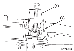
Fig. 26 Removing the Shift Socket Roll Pin
2 - SHIFT SOCKET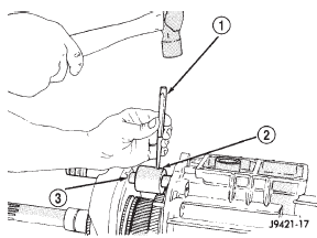
Fig. 27 Removing Shift Shaft Lever And Bushing Roll Pin
2 - BUSHING AND LEVER
3 - SHIFT SHAFT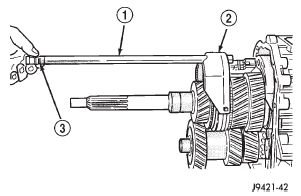
Fig. 28 Shift Shaft Removal
2 - 3-4 FORK
3 - SHAFT DETENT NOTCHES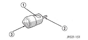
Fig. 29 Shift Socket And Roll Pin
2 - ROLL PIN
3 - SHIFT SOCKET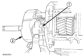
Fig. 30 Removing Shift Shaft Lever And Bushing
2 - 3-4 FORK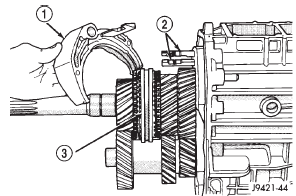
Fig. 31 Removing 3-4 Shift Fork
2 - 1-2 AND 5TH-REVERSE FORK ARMS
3 - 3-4 SYNCHRO SLEEVE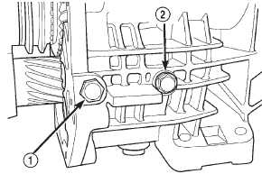
Fig. 32 Reverse Idler Shaft/Support
2 - SHAFT BOLT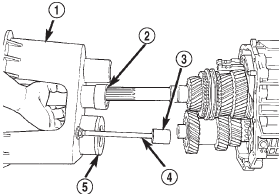
Fig. 33 Installing Assembly Fixture On Geartrain
2 - SPECIAL TOOL 6747-1A
3 - SPECIAL TOOL 8115
4 - REVERSE IDLER PEDESTAL
5 - SPECIAL TOOL 6747-2A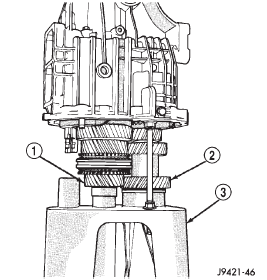
Fig. 34 Geartrain And Housing Mounted On Fixture Tool
2 - COUNTERSHAFT
3 - SPECIAL TOOL 6747
Fig. 35 Removing/Installing Output Shaft Bearing Retainer Bolts-2WD
Fig. 36 Unseating Rear Housing From Output Shaft Bearing-2WD
2 - PLASTIC OR RAWHIDE MALLET
3 - FIXTURE TOOL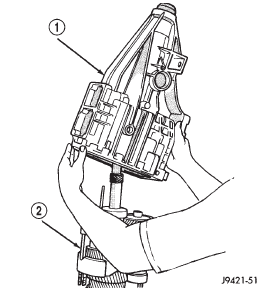
Fig. 37 Rear Housing Removal-2WD
2 - SHIFT FORKS AND GEARTRAIN
Fig. 38 Remove Countershaft Rear Bearing
2 - OUTPUT SHAFT
3 - COUNTER SHAFT
Fig. 39 Location Of Dimples In Seal Face-4WD
2 - SEAL FACE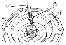
Fig. 40 Rear Seal Removal-4WD
2 - REMOVER TOOL
3 - REAR SEAL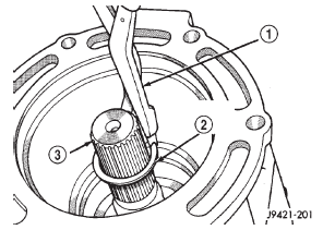
Fig. 41 Rear Bearing Snap Ring Removal-4WD
2 - REAR BEARING SNAP RING
3 - OUTPUT SHAFT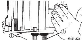
Fig. 42 Rear Adapter Housing Removal
2 - OUTPUT SHAF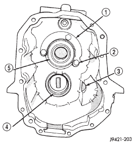
Fig. 43 Rear Adapter Housing Components
2 - RETAINER BOLTS (3)
3 - IDLER SHAFT NOTCH
4 - COUNTERSHAFT REAR BEARING RACE
5 - REAR BEARING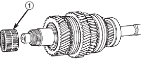
Fig. 44 Third Gear Needle Bearing Removal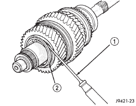
Fig. 45 Thrust Washer Retaining Ring Removal
2 - THRUST WASHER RETAINING RING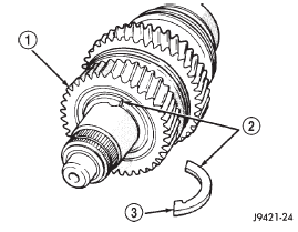
Fig. 46 Two-Piece Thrust Washer
2 - THRUST WASHER (2-PIECE)
3 - WASHER LOCATING LUG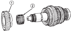
Fig. 47 Second Gear And Needle Bearing Removal
2 - SECOND GEAR NEEDLE BEARING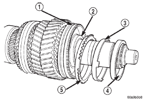
Fig. 48 Second Gear Synchro Ring And Cones Removal
2 - INTERM RING
3 - SYNCHRO FRICTION CONE
4 - SYNCHRO CONE
5 - SYNCHRO RING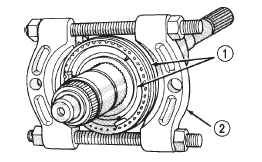
Fig. 49 Hub And Sleeve Removal-1-2 Synchro
2 - SPECIAL TOOL
1130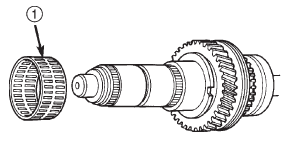
Fig. 50 First Gear Needle Bearing Removal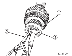
Fig. 51 Output Shaft Bearing Snap Ring Removal
2 - BEARING SNAP RING
3 - SNAP RING PLIERS
Fig. 52 Fifth Gear Removal
Fig. 53 Fifth Gear Needle Bearing Removal
Fig. 54 Fifth-Reverse Synchro Hub Snap Ring Removal
2 - SYNCHRO HUB SNAP RING
3 - SNAP RING PLIER
Fig. 55 Fifth-Reverse Synchro Hub And Sleeve Removal
2 - FIFTH-REVERSE SYNCHRO HUB AND SLEEVE
3 - REVERSE GEAR
4 - OUTPUT SHAFT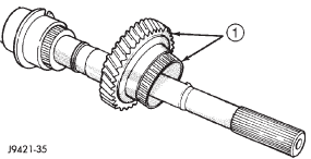
Fig. 56 Reverse Gear And Needle Bearing Removal
Fig. 57 Reverse Idler Components
2 - FLAT WASHER
3 - WAVE WASHER
4 - THRUST WASHER
5 - REVERSE IDLER GEAR
6 - IDLER GEAR BEARING
7 - IDLER SHAFT
8 - THRUST WASHER
9 - SNAP RING
10 - THRUST WASHER LOCK BALLS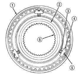
Fig. 58 Assembled View Of Synchro Compon
2 - HUB SHOULDER
3 - SPRING (3)
4 - STRUT (3)
5 - DETENT BALL (3)
6 - HUB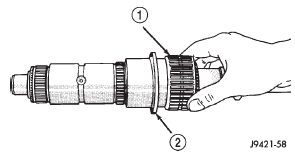
Fig. 59 Reverse Gear Bearing Installation
2 - SHOULDER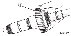
Fig. 60 Reverse Gear Installation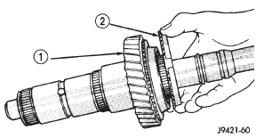
Fig. 61 Reverse Gear Synchro Ring Installation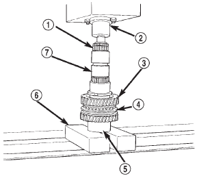
Fig. 62 Fifth-Reverse Synchro Assembly I
2 - PRESS RAM
3 - REVERSE GEAR
4 - FIFTH-REVERSE SYNCHRO ASSEMBLY
5 - SPECIAL TOOL
6310-1
6 - PRESS BLOCKS
7 - OUTPUT SHAFT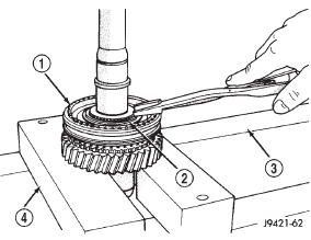
Fig. 63 Installing Fifth-Reverse Synchro Hub Snap Ring
2 - SNAP RING
3 - PRESS BED
4 - PRESS BLOCKS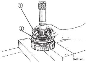
Fig. 64 Installing Fifth Gear Synchro Ring
2 - FIFTH-REVERSE SYNCHRO ASSEMBLY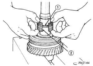
Fig. 65 Installing Fifth Gear Bearing
2 - FIFTH GEAR BEARING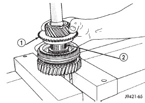
Fig. 66 Fifth Gear Installation
2 - BEARING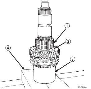
Fig. 67 First Gear Bearing Installation
2 - SHAFT SHOULDER
3 - SPECIAL TOOL
6310-1
4 - PRESS BLOCKS
Fig. 68 First Gear Installation
2 - SPECIAL TOOL
6310-1
3 - BEARING
Fig. 69 First Gear Synchro Ring Installation
2 - SPECIAL TOOL 6310-1
3 - FIRST GEAR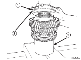
Fig. 70 Starting 1-2 Synchro On Shaft
2 - SPECIAL TOOL 6310-1
3 - BE SURE THIS IS "FIRST GEAR SIDE" OF SYNCHRO
SLEEVE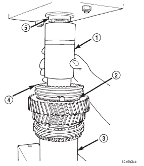
Fig. 71 Pressing 1-2 Synchro Assembly Onto Output Shaft
2 - SYNCHRO RING
3 - SPECIAL TOOL
6310-1
4 - 1-2 SYNCHRO ASSEMBLY
5 - PRESS RAM
Fig. 72 Installing 1-2 Synchro Hub Snap Ring
2 - SPECIAL TOOL
6310-1
3 - SYNCHRO SNAP RING
Fig. 73 Second Gear Synchro Ring Installation
2 - 1-2 SYNCHRO
3 - SPECIAL TOOL
6310-1
Fig. 74 Second Gear Bearing Installation
2 - SPECIAL TOOL
6310-1
Fig. 75 Second Gear Installation
2 - 1-2 SYNCHRO ASSEMBLY
3 - BEARING
4 - SECOND GEAR
Fig. 76 Installing Two-Piece Thrust Washer
2 - LUG BORE
3 - THRUST WASHER LUGS
4 - LUG BORE
5 - LUG
6 - WASHER HALF
Fig. 77 Starting Retaining Ring Over Two-Piece Thrust Washer
2 - THRUST WASHER HALVES
3 - SECOND GEAR
4 - LOCATING DIMPLE
Fig. 78 Seating Thrust Washer Retaining Ring
2 - THRUST WASHER RETAINING RING
Fig. 79 Third Gear Bearing Installation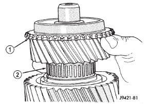
Fig. 80 Installing Third Gear
2 - BEARING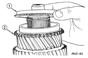
Fig. 81 Third Speed Synchro Ring Installation
2 - THIRD GEAR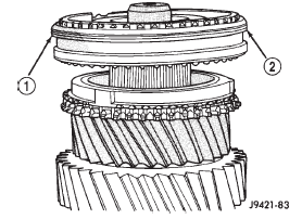
Fig. 82 Starting 3-4 Synchro Hub On Output Shaft
2 - 3-4 SYNCHRO ASSEMBLY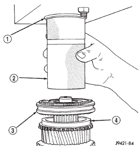
Fig. 83 Pressing 3-4 Synchro Assembly On Output Shaft
2 - PIPE TOOL
3 - 3-4 SYNCHRO
4 - THIRD SPEED SYNCHRO RIN
Fig. 84 Installing 3-4 Synchro Hub Snap Ring
2 - HEAVY DUTY SNAP RING PLIERS
Fig. 85 Installing Output Shaft Bearing Snap Ring
2 - HEAVY DUTY SNAP RING PLIERS
Fig. 86 Correct Synchro Sleeve Position
2 - GROOVE FORWARD
3 - FIRST GEAR SIDE MARKING TOWARD FIRST GEAR
4 - TAPER FORWARD
5 - GROOVE FORWARD
6 - 5TH-REV SYNCHRO SLEEVE
7 - 1-2 SYNCHRO SLEEVE
8 - 3-4 SYNCHRO SLEEVE
Fig. 87 Idler Gear And Bearing Installation
2 - BEARING
3 - LOCK BALL
4 - REAR OF SHAFT
Fig. 88 Idler Gear Rear Thrust Washer Installation
2 - SNAP RING GROOVE
3 - THRUST WASHER
Fig. 89 Idler Gear And Shaft Assembly
2 - GEAR
3 - THRUST WASHER AND BALL
4 - WAVE WASHER
5 - FLAT WASHER
6 - FRONT OF SHAFT
7 - SNAP RING
8 - SNAP RING
Fig. 90 Preparing Assembly Fixture For Geartrain Build-up
2 - SPECIAL TOOL 8115
3 - SPECIAL TOOL 6747-1A
4 - SPECIAL TOOL 6747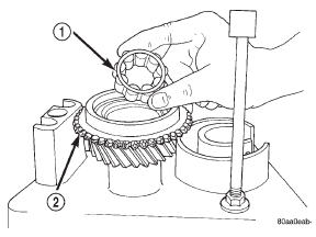
Fig. 91 Installing Pilot Bearing In Input Shaft
2 - INPUT SHAFT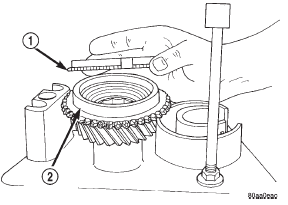
Fig. 92 Installing Fourth Gear Synchro Ring On Input Shaft
2 - INPUT SHAFT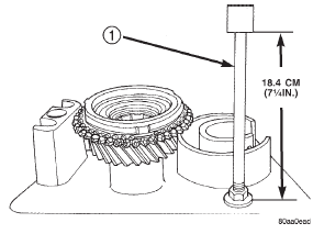
Fig. 93 Idler Pedestal Basic Height Adjus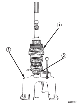
Fig. 94 Output Shaft And Geartrain Installed In Input Shaft
2 - INPUT SHAFT
3 - SPECIAL TOOL
6747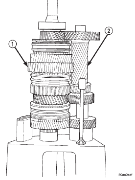
Fig. 95 Countershaft Installed On Fixture Tool
2 - COUNTERSHAFT (SLIDE INTO PLACE ON FIXTURE TOOL)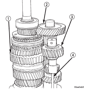
Fig. 96 Reverse Idler Assembly Positioned On Assembly Fixture Pedestal
2 - COUNTERSHAFT
3 - REVERSE IDLER ASSEMBLY
4 - TOOL PEDESTAL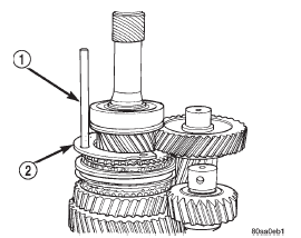
Fig. 97 Positioning Output Shaft Bearing Retainer For Rear Housing
Installation
2 - OUTPUT SHAFT BEARING RETAINER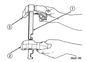
Fig. 98 Assembling 1-2 And Fifth-Reverse Shift Forks
2 - 1-2 FORK
3 - FIFTH-REVERSE FORK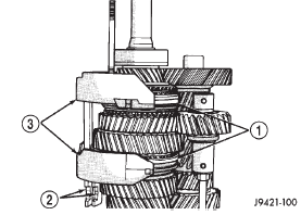
Fig. 99 Shift Forks Installed In Synchro Sleeves
2 - FORK ARMS
3 - SHIFT FORKS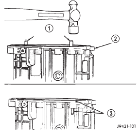
Fig. 100 Preparing Rear Housing Dowels For Installation
2 - REAR HOUSING
3 - DOWEL FLUSH WITH SURFACE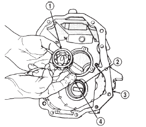
Fig. 101 Lubricating Countershaft Rear Bearing
2 - REAR BEARING RACE
3 - REAR HOUSING
4 - PETROLEUM JELLY (APPLY TO BEARING AND RACE)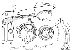
Fig. 102 Countershaft Rear Bearing Seated In Seated in Race
2 - COUNTERSHAFT REAR BEARING (SEATED IN RACE)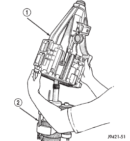
Fig. 103 Rear Housing Installation-2WDOther materials:
Ignition system
DESCRIPTION
Two different ignition systems are used. One type
is used for the 2.5L 4-cylinder engine. The other is
used for the 4.0L 6-cylinder engine.
OPERATION
2.5L 4-Cylinder Engine:
The ignition system is controlled by the Powertrain
Control Module (PCM).
The ignition s ...

