Jeep Cherokee (XJ): Disassembly and assembly. Cleaning and inspection. Specifications
CYLINDER BLOCK DISASSEMBLY (1) Drain the engine oil. Remove and discard the
oil filter.
(2) Remove the water pump from the cylinder
block.
(3) Remove the distributor from the cylinder block.
(4) Remove the vibration damper.
(5) Remove the timing case cover and lay the cover
upside down.
(6) Position a drift punch into the slot in the back
of the cover and tap the old seal out.
(7) Remove the timing chain bumper.
(8) Remove the oil slinger from crankshaft.
(9) Remove the camshaft retaining bolt and
remove the sprockets and chain as an assembly.
(10) Remove the camshaft.
(11) Remove the oil pan and gasket.
(12) Remove the timing chain tensioner.
(13) Remove the front and rear oil galley plugs.
(14) Remove the connecting rods and the pistons.
Remove the connecting rod and piston assemblies
through the top of the cylinder bores.
(15) Remove the crankshaft. ASSEMBLY (1) Install the crankshaft.
(2) Install the connecting rods and the pistons
through the top of the cylinder bores.
(3) Install the front and rear oil galley plugs.
(4) Install the timing chain tensioner.
(5) Install the camshaft.
(6) Install the sprockets and chain as an assembly.
(7) Install the oil slinger to the crankshaft.
(8) Install the timing chain bumper.
(9) Install the timing case cover seal.
(10) Install the timing case cover.
(11) Install the oil pan gasket and oil pan.
(12) Install the vibration damper.
(13) Install the water pump. Tighten the mounting
bolts to 31 N·m (270 in. lbs.) torque.
(14) Remove the distributor from the cylinder
block.
(15) Lubricate the oil filter seal with clean engine
oil. Tighten oil filter to 18 N·m (13 ft. lbs.) torque.
(16) Install the engine into the vehicle.
(17) Fill the engine with clean lubrication oil.
(18) Fill the cooling system. CLEANING Clean all the components with cleaning solvent.
Use compressed air to blow out the oil passages in
the rocker arms and push rods. INSPECTION Inspect the pivot surface area of each rocker arm.
Replace any that are scuffed, pitted, cracked or
excessively worn Inspect the valve stem tip contact surface of each rocker
arm and replace any rocker arm that is deeply pitted.
Inspect each push rod end for excessive wear and
replace as required. If any push rod is excessively
worn because of lack of oil, replace it and inspect the
corresponding hydraulic tappet for excessive wear.
Inspect the push rods for straightness by rolling
them on a flat surface or by shining a light between
the push rod and the flat surface.
A wear pattern along the length of the push rod is
not normal. Inspect the engine cylinder head for
obstruction if this condition exists. CLEANING Thoroughly clean the engine cylinder head and cylinder
block mating surfaces. Clean the intake and
exhaust manifold and engine cylinder head mating
surfaces. Remove all gasket material and carbon.
Check to ensure that no coolant or foreign material
has fallen into the tappet bore area.
Remove the carbon deposits from the combustion
chambers and top of the pistons. INSPECTION Use a straightedge and feeler gauge to check the
flatness of the engine cylinder head and block mating
surfaces. CLEANING Thoroughly clean the oil pan and engine block gasket
surfaces.
Use compressed air to clean out: Once the block has been completely cleaned, apply
Mopart Thread Sealant with Teflon to the threads of
the front and rear oil galley plugs. Tighten the plugs
to 41 N·m (30 ft. lbs.) torque. INSPECTION Inspect the cylinder bores for signs of scorring, pitting
or cracks. If the cylinder bores are scorred or
pitted the cylinder bores will require boreing or honing
to clean them up. Refer to Honing Cylinder Bores
in this Section. If the cylinder bore(s) are cracked the
cylinder block must be replaced.
Inspect the cylinder block to cylinder head mating
surface for flatness and/or pitting.
1 - FILTER BYPASS HOLE
1 - FRONT OIL GALLEY HOLE
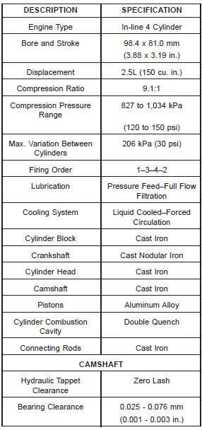
Fig. 91 Rear Oil Galley Hole 1 - REAR OIL GALLEY HOLE ENGINE DESCRIPTION
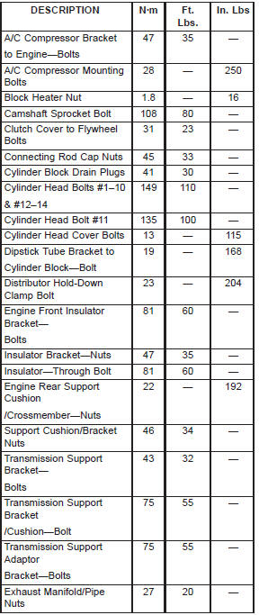
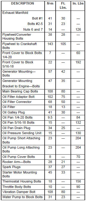
TORQUE CHART 2.5L ENGINE
Disassembly and assembly
Cleaning and inspection
Rocker arms and push rods
Engine cylinder head
Cylinder block
Fig. 89 Oil Filter Adaptor Hole
2 - OIL FILTER ADAPTOR HOLE
Fig. 90 Front Oil Galley Hole
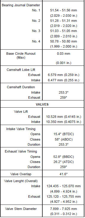
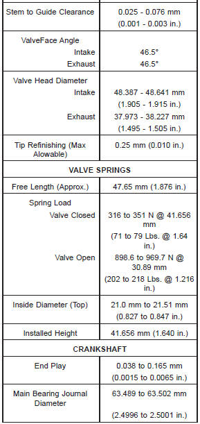
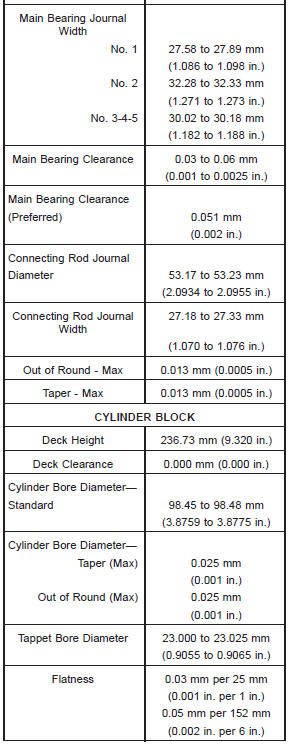
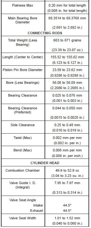
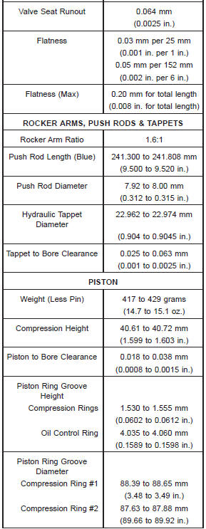
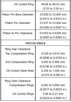
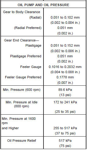
Specifications
Engine specifications
Specifications-torque
 Oil pump. Piston and connecting rod. Rear main oil seal

Other materials:
Instrument panel features
1 - Air Demister Outlet
2 - Air Outlet
3 - EVIC/DID Display Controls
4 - Horn/Driver Air Bag
5 - Instrument Cluster
6 - Cruise Controls
7 - Storage Compartment
8 - Radio
9 - Passenger Air Bag
10 - Glove Compartment
11 - Lower Switch Bank
12 - Uconnect Feature Controls
- If Equipped
...