Jeep Cherokee (XJ): Disassembly and assembly
DISASSEMBLY (1) Unseat and remove retaining ring from groove
with a punch through the hole in the end of the
housing (Fig. 2).
1 - RETAINING RING (2) Slowly rotate stub shaft with 12 point socket
COUNTER-CLOCKWISE to force the end plug out
from housing.
CAUTION: Do not turn stub shaft any further than
necessary. The rack piston balls will drop out of the
rack piston circuit if the stub shaft is turned too far.
(3) Remove O-ring from the housing (Fig. 3). ASSEMBLY (1) Lubricate O-ring with power steering fluid and
install into the housing.
(2) Install end plug by tapping the plug lightly
with a plastic mallet into the housing.
(3) Install retaining ring so one end of the ring
covers the housing access hole (Fig. 4). DISASSEMBLY (1) Clean exposed end of pitman shaft and housing
with a wire brush.
(2) Remove preload adjuster nut (Fig. 5).
1 - HOUSING ASSEMBLY
1 - RING CAP (3) Rotate the stub shaft with a 12 point socket
from stop to stop and count the number of turns.
(4) Center the stub shaft by rotating it from the
stop 1/2 of the total amount of turns.
(5) Remove side cover bolts and remove side cover,
gasket and pitman shaft as an assembly (Fig. 5). NOTE: The pitman shaft will not clear the housing
if it is not centered
1 - SIDE COVER BOLTS (6) Remove pitman shaft from the side cover.
(7) Remove dust seal from the housing with a seal
pick (Fig. 6).
CAUTION: Use care not to score the housing bore
when prying out seals and washer.
(8) Remove retaining ring with snap ring pliers.
(9) Remove washer from the housing.
(10) Remove oil seal from the housing with a seal
pick.
(11) Remove pitman shaft bearing from housing
with a bearing driver and handle (Fig. 7). ASSEMBLY (1) Install pitman shaft bearing into housing with
a bearing driver and handle.
(2) Coat the oil seal and washer with special
grease supplied with the new seal.
(3) Install the oil seal with a driver and handle.
(4) Install backup washer.
1 - BEARING
1 - REMOVER (6) Coat the dust seal with special grease supplied
with the new seal.
(7) Install dust seal with a driver and handle.
(8) Install pitman shaft to side cover by screwing
shaft in until it fully seats to side cover.
(9) Install preload adjuster nut. Do not tighten
nut until after Over-Center Rotation Torque
adjustment has been made.
(10) Install gasket to side cover and bend tabs
around edges of side cover (Fig. 5).
(11) Install pitman shaft assembly and side cover
to housing.
(12) Install side cover bolts and tighten to 60 N·m
(44 ft. lbs.).
(13) Perform over-center rotation torque adjustment. DISASSEMBLY (1) Remove lock nut (Fig. 8).
(2) Remove adjuster nut with Spanner Wrench
C-4381.
(3) Remove thrust support assembly out of the
housing (Fig. 9).
(4) Pull stub shaft and valve assembly from the
housing (Fig. 10).
1 - ADJUSTER NUT (5) Remove stub shaft from valve assembly by
lightly tapping shaft on a block of wood to loosen
shaft. Then disengage stub shaft pin from hole in
spool valve and separate the valve assembly from
stub shaft (Fig. 11).
(6) Remove spool valve from valve body by pulling
and rotating the spool valve from the valve body (Fig.
12).
(7) Remove spool valve O-ring and valve body
teflon rings and O-rings underneath the teflon rings
(Fig. 13).
1 - STUB SHAFT
1 - GEAR (8) Remove the O-ring between the worm shaft
and the stub shaft. ASSEMBLY NOTE: Clean and dry all components, then lubricate
with power steering fluid.
(1) Install spool valve spool O-ring.
(2) Install spool valve in valve body by pushing
and rotating. Hole in spool valve for stub shaft pin
must be accessible from opposite end of valve body.
1 - STUB SHAFT
1 - SPOOL VALVE (3) Install stub shaft in valve spool and engage
locating pin on stub shaft into spool valve hole (Fig.
14). NOTE: Notch in stub shaft cap must fully engage
valve body pin and seat against valve body shoulder.
1 - O-RING SEALS
1 - NOTCH IN CAP (4) Install O-rings and teflon rings over the
O-rings on valve body.
(5) Install O-ring into the back of the stub shaft
cap (Fig. 15).
1 - VALVE BODY (6) Install stub shaft and valve assembly in the
housing. Line up worm shaft to slots in the valve
assembly.
(7) Install thrust support assembly.
NOTE: The thrust support is serviced as an assembly.
If any component of the thrust support is damaged
the assembly must be replaced.
(8) Install adjuster nut and lock nut.
(9) Adjust Thrust Bearing Preload and Over-Center
Rotating Torque. DISASSEMBLY (1) Remove housing end plug.
(2) Remove rack piston plug (Fig. 16).
(3) Remove side cover and pitman shaft.
(4) Turn stub shaft COUNTERCLOCKWISE until
the rack piston begins to come out of the housing.
(5) Insert Arbor C-4175 into bore of rack piston
(Fig. 17) and hold tool tightly against worm shaft.
(6) Turn the stub shaft with a 12 point socket
COUNTERCLOCKWISE, this will force the rack piston
onto the tool and hold the rack piston balls in
place.
(7) Remove the rack piston and tool together from
housing.
(8) Remove tool from rack piston.
(9) Remove rack piston balls.
(10) Remove clamp bolts, clamp and ball guide
(Fig. 18).
(11) Remove teflon ring and O-ring from the rack
piston (Fig. 19).
1 - EXTENSION
1 - RACK PISTON (12) Remove the adjuster lock nut and adjuster
nut from the stub shaft.
(13) Pull the stub shaft with the spool valve and
thrust support assembly out of the housing.
(14) Remove the worm shaft from the housing
(Fig. 20).
1 - CLAMP
1 - TEFLON SEAL ASSEMBLY NOTE: Clean and dry all components and lubricate
with power steering fluid.
(1) Check for scores, nicks or burrs on the rack
piston finished surface. Slight wear is normal on the
worm gear surfaces.
1 - GEAR HOUSING (2) Install O-ring and teflon ring on the rack piston.
(3) Install worm shaft in the rack piston and align
worm shaft spiral groove with rack piston ball guide
hole (Fig. 21).
1 - INSTALL BALLS IN THIS HOLE WHILE SLOWLY ROTATING
WORM COUNTER CLOCKWISE CAUTION: The rack piston balls must be installed
alternately into the rack piston and ball guide. This
maintains worm shaft preload. There are 12 black
balls and 12 silver (Chrome) balls. The black balls
are smaller than the silver balls.
(4) Lubricate and install rack piston balls through
return guide hole while turning worm shaft COUNTERCLOCKWISE
(Fig. 21).
(5) Install remaining balls in guide using grease to
hold the balls in place (Fig. 22).
1 - GUIDE (6) Install the guide onto rack piston and install
clamp and clamp bolts. Tighten bolts to 4.8 N·m (43
in. lbs.).
(7) Insert Arbor C-4175 into bore of rack piston
and hold tool tightly against worm shaft.
(8) Turn the worm shaft COUNTERCLOCKWISE
while pushing on the arbor. This will force the rack
piston onto the arbor and hold the rack piston balls
in place.
(9) Install the races and thrust bearing on the
worm shaft and install shaft in the housing (Fig. 20).
(10) Install the stub shaft with spool valve, thrust
support assembly and adjuster nut in the housing.
(11) Install the rack piston and arbor tool into the
housing.
(12) Hold arbor tightly against worm shaft and
turn stub shaft CLOCKWISE until rack piston is
seated on worm shaft.
(13) Install pitman shaft and side cover in the
housing.
(14) Install rack piston plug and tighten to 150
N·m (111 ft. lbs.).
(15) Install housing end plug.
(16) Adjust worm shaft thrust bearing preload and
over-center rotating torque.Housing end plug
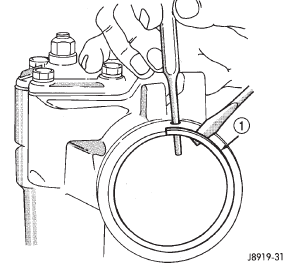
Fig. 2 End Plug Retaining RingPitman shaft/seals/bearing
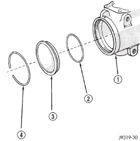
Fig. 3 End Plug Components
2 - HOUSING END PLUG O-RING SEAL
3 - HOUSING END PLUG
4 - RETAINING RING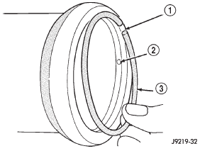
Fig. 4 Installing The Retaining Ring
2 - PUNCH ACCESS HOLE
3 - RETAINER RING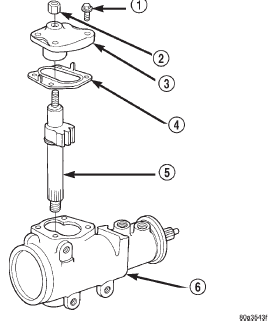
Fig. 5 Side Cover and Pitman Shaft
2 - PRELOAD ADJUSTER NUT
3 - SIDE COVER
4 - GASKET SEAL
5 - PITMAN SHAFT GEAR
6 - HOUSING ASSEMBLY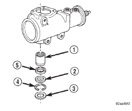
Fig. 6 Pitman Shaft Seals & Bearing
2 - WASHER
3 - DUST SEAL
4 - RETAINER
5 - OIL SEAL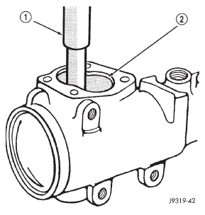
Fig. 7 Needle Bearing Removal
2 - SIDE COVER AREASpool valve
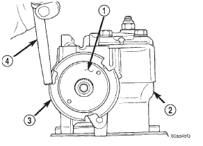
Fig. 8 Lock Nut and Adjuster Nut
2 - STEERING GEAR
3 - LOCK NUT
4 - PUNCH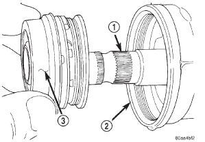
Fig. 9 Thrust Support Assembly
2 - HOUSING
3 - THRUST SUPPORT ASSEMBLY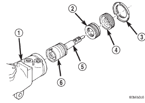
Fig. 10 Valve Assembly With Stub Shaft
2 - THRUST SUPPORT
3 - LOCK NUT
4 - ADJUSTER NUT
5 - STUB SHAFT
6 - VALVE ASSEMBLY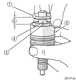 БЮ
Fig. 11 Stub Shaft
БЮ
Fig. 11 Stub Shaft
2 - VALVE BODY
3 - HOLE IN SPOOL
4 - SHAFT PIN
5 - 6mm (1/4")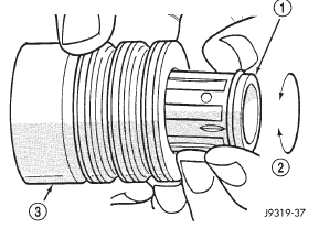
Fig. 12 Spool Valve
2 - ROTATE VALVE TO REMOVE
3 - VALVE BODY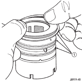
Fig. 13 Valve Seals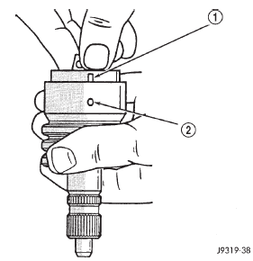
Fig. 14 Stub Shaft Installation
2 - VALVE BODY PIN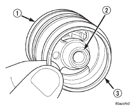
Fig. 15 Stub Shaft Cap O-Ring
2 - STUB SHAFT CAP
3 - O-RINGRack piston and worm shaft
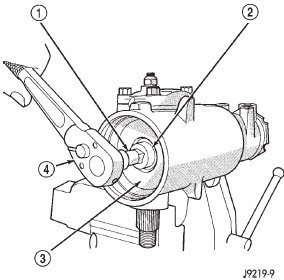
Fig. 16 Rack Piston End Plug
2 - END PLUG
3 - RACK PISTON
4 - RATCHET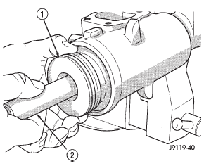
Fig. 17 Rack Piston with Arbor
2 - SPECIAL TOOL C-4175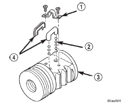
Fig. 18 Rack Piston
2 - BALLS
3 - RACK PISTON
4 - BALL GUIDE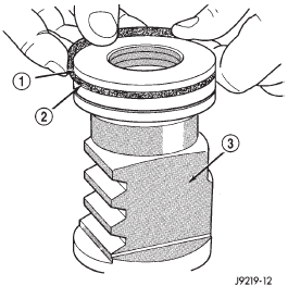
Fig. 19 Rack Piston Teflon Ring and O-Ring
2 - BACK-UP O-RING MUST BE INSTALLED UNDER PISTON
RING
3 - RACK PISTON NUT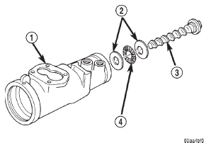
Fig. 20 Worm Shaft
2 - BEARING RACE
3 - WORM SHAFT
4 - BEARING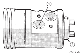
Fig. 21 Installing Balls in Rack Piston
2 - WORM FLANGE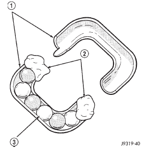
Fig. 22 Balls in the Return Guide
2 - PETROLEUM JELLY
3 - BALLS
 Description and operation. Diagnosis and testing. Removal and installation

Other materials:
Power steering
Description and operation
STEERING SYSTEM
DESCRIPTION
The power steering system has a hydraulic pump.
The pump is a constant flow rate and displacement,
vane-type pump. The pump on the 4.0L engine has a
reservoir mounted to it (Fig. 1). The 2.5L engine has
a remote mounted reservoir.
The ...