Jeep Cherokee (XJ): Disassembly and assembly. Specifications
HYDRAULIC CONTROL UNIT/CONTROLLER
ANTILOCK BRAKE DISASSEMBLY (1) Remove pump motor connector from the CAB.
(2) Remove CAB mounting screws from the HCU
(Fig. 13).
(3) Remove CAB from the HCU.
1 - MOUNTING SCREWS ASSEMBLY (1) Install the CAB onto the HCU.
(2) Install the CAB mounting screws and tighten
to 1.8 N·m (16 in. lbs.).
(3) Install pump motor connector to the CAB. T0RQUE CHART DESCRIPTION TORQUE G-Sensor Sensor Bolt . . . . . . . . . . . . . . 3 N·m (27.5 in. lbs.) Brakes Mounting Nuts . . . . . . . . . 11.5 N·m (102 in. lbs.) Controller Antilock Brakes Mounting Screws . . . . . . . . . 1.8 N·m (16 in. lbs.) Wheel Speed Sensors Front Mounting Bolt . . . . . . 4.7 N·m (42 in. lbs.)Disassembly and assembly
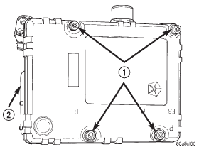
Fig. 13 CAB Mounting Screws
2 - CABSpecifications
Bracket Bolt . . . . . . . . . . . . . 2.7 N·m (24 in. lbs.)
Hydraulic Control Unit/Controller Antilock
Brake Lines . . . . . . . . . . . . . 19 N·m (170 in. lbs.)
Rear Mounting Bolt . . . . . . . 13 N·m (115 in. lbs.)
 Diagnosis and testing. Service procedures. Removal and installation

Other materials:
181 FBI pinion gear depth
GENERAL INFORMATION
Ring and pinion gears are supplied as matched
sets only. The identifying numbers for the ring and
pinion gear are etched into the face of each gear (Fig.
71). A plus (+) number, minus (-) number or zero (0)
is etched into the face of the pinion gear. This number
is the am ...