Jeep Cherokee (XJ): Engine mounts-front. Engine mount-rear. Engine assembly
The front mounts support the engine at each side.
These supports are made of resilient rubber. REMOVAL (1) Disconnect negative cable from battery.
(2) Raise the vehicle.
(3) Support the engine.
(4) Remove the nut from the through bolt (Fig. 44).
DO NOT remove the through bolt.
(5) Remove the retaining bolts and nuts from the
support cushions (Fig. 44).
(6) Remove the through bolt.
(7) Remove the support cushions. INSTALLATION (1) If the engine support bracket was removed,
position the bracket onto the block and install the
attaching bolts (Fig. 44). Tighten the engine support
bracket bolts to 61 N·m (45 ft. lbs.) torque.
(2) If the support cushion bracket was removed,
position the bracket onto the lower front sill (Fig.
45). Install support cushion bracket bolts and nuts.
Tighten the bolts to 54 N·m (40 ft. lbs.) torque.
Tighten the nuts to 41 N·m (30 ft. lbs.) torque.
(3) Place the support cushion into position on the
support cushion bracket (Fig. 44). Install and tighten
the bolts and nuts to 41 N·m (30 ft. lbs.) torque.
(4) Install the through bolt and the retaining nut
(Fig. 44). Tighten the through bolt nut to 65 N·m (48
ft. lbs.) torque.
1 - ENGINE SUPPORT BRACKET (5) Remove the engine support.
(6) Lower the vehicle.
(7) Connect negative cable to battery. A resilient rubber cushion supports the transmission
at the rear between the transmission extension
housing and the rear support crossmember or skid
plate. REMOVAL (1) Disconnect negative cable from battery.
(2) Raise the vehicle and support the transmission.
(3) Remove the nuts holding the support cushion
to the crossmember (Fig. 46) (Fig. 47). Remove the
crossmember.
1 - SUPPORT CUSHION BRACKET MANUAL TRANSMISSION (Fig. 46)
a. Remove the support cushion nuts and remove
the cushion.
b. Remove the transmission support bracket bolts
and remove the bracket from the transmission. AUTOMATIC TRANSMISSION (Fig. 47)
a. Remove the support cushion bolts and remove
the cushion and the support bracket from the transmission
(4WD) or from the adaptor bracket (2WD).
b. On 2WD vehicles, remove the bolts holding the
transmission support adaptor bracket to the transmission
(Fig. 47). Remove the adaptor bracket. INSTALLATION MANUAL TRANSMISSION: a. Install the transmission support bracket to the
transmission. Install the bolts and tighten to 46 N·m
(34 ft. lbs.) torque.
1 - TRANSMISSION SUPPORT BRACKET b. Install the support cushion to the support
bracket. Install the nuts and tighten to 75 N·m (55
ft. lbs.) torque. AUTOMATIC TRANSMISSION: a. On 2WD vehicles, position the transmission
support adaptor bracket to the transmission. Install
the bolts and tighten to 75 N·m (55 ft. lbs.) torque.
b. Position the transmission support bracket and
support cushion to the adaptor bracket (2WD) or the
transmission (4WD). Install the bolts and tighten to
75 N·m (55 ft. lbs.) torque.
(1) Position the crossmember onto the support
cushion studs. Install the stud nuts and tighten to 22
N·m (192 in. lbs) torque.
(2) Install crossmember-to-sill bolts and tighten to
41 N·m (30 ft. lbs.) torque.
(3) Remove the transmission support.
(4) Lower the vehicle.
(5) Connect negative cable to battery. REMOVAL (1) Disconnect the battery cables. Remove the battery.
(2) Mark the hinge locations on the hood panel for
alignment reference during installation. Remove the
engine compartment lamp. Remove the hood.
1 - 434 WARNING: THE COOLANT IN A RECENTLY OPERATED
ENGINE IS HOT AND PRESSURIZED. USE
CARE TO PREVENT SCALDING BY HOT COOLANT.
CAREFULLY RELEASE THE PRESSURE BEFORE
REMOVING THE RADIATOR DRAIN COCK AND CAP.
(3) Remove the air cleaner assembly.
(4) Loosen the radiator drain cock and radiator cap
to drain the coolant. DO NOT waste usable coolant.
If the solution is clean, drain the coolant into a clean
container for reuse.
(5) Remove the lower radiator hose.
(6) Remove the upper radiator hose and coolant
recovery hose (Fig. 48).
(7) Remove upper radiator support retaining bolts
and remove radiator support.
(8) Remove the fan shroud (Fig. 48) and electric
cooling fan.
(9) Disconnect the transmission fluid cooler tubing
(automatic transmission). (10) Disconnect radiator fan switch wire connector.
(11) Vehicles with Air Conditioning:
(a) Discharge A/C system (refer to group 24,
Heating and Air Conditioning for proper procedures)
(b) Disconnect the suction/discharge hose and
cap off compressor ports to prevent foreign material
and refrigerant oil loss.
(12) Remove the radiator or radiator and condenser
(if equipped with A/C).
(13) Remove the fan assembly from the idler pulley.
(14) Disconnect the heater hoses at the engine
thermostat housing and water pump (Fig. 48) (Fig.
49).
1 - UPPER RADIATOR HOSE (15) Disconnect the throttle cable.
(16) Disconnect the speed control cable (if
equipped).
(17) Disconnect the line pressure cable (if equipped
with automatic transmission).
(18) Disconnect the fuel injector harness at the
injectors.
(19) Disconnect the distributor electrical connection
and the oil pressure switch connector.
WARNING: THE FUEL SYSTEM IS UNDER A CONSTANT
PRESSURE (EVEN WITH THE ENGINE
TURNED OFF). BEFORE DISCONNECTING FUEL
LINES, THE FUEL SYSTEM PRESSURE MUST BE
RELEASED.
(20) Perform the Fuel System Pressure Release
procedure (refer to Group 14, Fuel System).
1 - HEATER HOSES (21) Remove the latch clip and disconnect fuel supply
line.
(22) Remove the power brake vacuum check valve
from the booster, if equipped.
(23) If equipped with power steering :
(a) Disconnect the hoses from the fittings at the
steering gear.
(b) Drain the pump reservoir.
(c) Cap the fittings on the hoses and steering
gear to prevent foreign objects from entering the
system.
(24) Identify, tag and disconnect all necessary wire
connectors and vacuum hoses.
(25) Raise and support the vehicle.
(26) Disconnect the wires from the starter motor
solenoid.
(27) Remove the starter motor.
(28) Disconnect the exhaust pipe from the manifold.
(29) Disconnect the engine speed sensor wire connection.
(30) Remove the exhaust pipe support.
(31) Remove the flywheel and converter housing
access cover.
(32) Vehicles with Automatic Transmission:
(a) Mark the converter and drive plate location.
(b) Remove the converter-to-drive plate bolts.
(33) Remove the upper flywheel and converter
housing bolts and loosen the bottom bolts.
(34) Remove the engine mount cushion-to-engine
compartment bracket bolts.
(35) Lower the vehicle.
(36) Attach a lifting device to the engine.
(37) Raise the engine off the front supports.
(38) Place a support or floor jack under the converter
(or flywheel) housing. (39) Remove the remaining converter (or flywheel)
housing bolts.
(40) Lift the engine out of the engine compartment. INSTALLATION CAUTION: When installing the engine into a vehicle
equipped with an automatic transmission, be careful
not to damage the trigger wheel on the flywheel.
(1) Attach a lifting device to the engine and lower
the engine into the engine compartment. For easier
installation, it may be necessary to remove the
engine mount cushions from the engine mount
bracket as an aide in alignment of the engine to the
transmission.
(2) Vehicles with Manual Transmission:
(a) Insert the transmission shaft into the clutch
spline.
(b) Align the flywheel housing with the engine.
(c) Install and tighten the flywheel housing
lower bolts finger tight.
(3) Vehicles with Automatic Transmission:
(a) Align the transmission torque converter
housing with the engine.
(b) Loosely install the converter housing lower
bolts and install the next higher bolt and nut on
each side.
(c) Tighten all 4 bolts finger tight.
(4) Install the engine mount cushions (if removed).
(5) Lower the engine and engine mount cushions
onto the engine compartment brackets. Install the
bolts and finger tighten the nuts.
(6) Remove the engine lifting device.
(7) Raise and support the vehicle.
(8) Install the remaining flywheel and converter
housing bolts. Tighten all bolts to 38 N·m (28 ft. lbs.)
torque.
(9) Vehicles with Automatic Transmission:
(a) Install the converter-to-drive plate bolts.
(b) Ensure the installation reference marks are
aligned.
(10) Install the flywheel and converter housing
access cover.
(11) Install the exhaust pipe support and tighten
the screw.
(12) Tighten the engine mount-to-bracket bolts.
(13) Connect the engine speed sensor wire connections
and tighten the screws.
(14) Connect the exhaust pipe to the manifold.
(15) Install the starter motor and connect the
cable.
(16) Connect the wires to the starter motor solenoid.
(17) Lower the vehicle.
(18) Connect all the vacuum hoses and wire connectors
identified during engine removal.
(19) Vehicles with Power Steering:
(a) Remove the protective caps
(b) Connect the hoses to the fittings at the steering
gear. Tighten the nut to 52 N·m (38 ft. lbs.)
torque.
(c) Fill the pump reservoir with fluid.
(20) Install the power brake vacuum check valve
to the booster, if equipped.
(21) Connect the fuel supply hose the fuel rail.
Push until a "click" is heard. Install latch clip
(22) Connect the fuel injector harness to the injectors.
(23) Connect the distributor electrical connector
and oil pressure switch connector.
(24) Connect the line pressure cable (if equipped
with automatic transmission).
(25) Connect the speed control cable, if equipped.
(26) Connect the throttle cable.
(27) Connect the heater hoses at the engine thermostat
housing and water pump.
(28) Install the fan assembly to the idler pulley.
(29) Connect the suction/discharge hose to the
compressor.
(30) Connect automatic transmission fluid cooler
lines, if equipped.
(31) Install the fan shroud, electric cooling fan and
radiator and condenser (if equipped with A/C).
(32) Connect the electric fan connector.
(33) Install upper radiator support.
(34) Connect the upper radiator hose.
(35) Connect the lower radiator hose.
(36) Align the hood to the scribe marks. Install the
hood.
(37) Install the air cleaner assembly.
(38) Install the battery and connect the battery
cable.
(39) Add the proper amount of engine oil and coolant.
WARNING: USE EXTREME CAUTION WHEN THE
ENGINE IS OPERATING. DO NOT STAND IN A
DIRECT LINE WITH THE FAN. DO NOT PUT YOUR
HANDS NEAR THE PULLEYS, BELTS OR FAN. DO
NOT WEAR LOOSE CLOTHING.
(40) Start the engine, inspect for leaks and correct
the fluid levels, as necessary.
(41) Charge the air conditioning system (refer to
Group 24, Heating and Air Conditioning for proper
procedures).Engine mounts-front
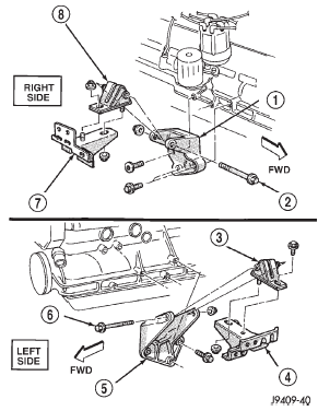
Fig. 44 Front Mounts
2 - THROUGH BOLT
3 - SUPPORT CUSHION
4 - SUPPORT CUSHION BRACKET
5 - ENGINE SUPPORT BRACKET
6 - THROUGH BOLT
7 - SUPPORT CUSHION BRACKET
8 - SUPPORT CUSHIONEngine mount-rear
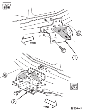
Fig. 45 Support Cushion Bracket
2 - SUPPORT CUSHION BRACKET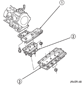
Fig. 46 Rear Mount(Manual Transmission)
2 - SUPPORT CUSHION
3 - CROSSMEMBER ASSEMBLYEngine assembly
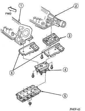
Fig. 47 Rear Mount(Automatic Transmission)
2 - 234
3 - TRANSMISSION SUPPORT ADAPTOR BRACKET
4 - SUPPORT CUSHION
5 - CROSSMEMBER ASSEMBLY
6 - TRANSMISSION SUPPORT BRACKET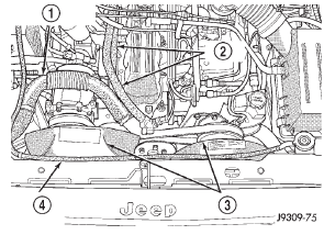
Fig. 48 Upper Radiator Hose, Coolant Recovery
Hose, Fan Shroud & Heater hoses
2 - HEATER HOSES
3 - FAN SHROUDS
4 - COOLANT RECOVERY HOSE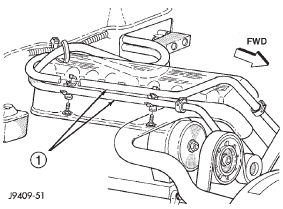
Fig. 49 Heater Hoses (RH Drive Vehicle)


Other materials:
Adding fuel
The gas cap is located behind the fuel filler door, on the
passenger side of the vehicle. If the gas cap is lost or
damaged, be sure the replacement cap has been designed
for use with this vehicle.
NOTE: When removing the fuel filler cap, lay the cap
tether in the hook, located on the fuel fill ...