Jeep Cherokee (XJ): Exhaust manifold. Cylinder head cover. Rocker arms and push rods
REMOVAL (1) Disconnect the battery negative cable.
(2) Raise the vehicle.
(3) Disconnect the exhaust pipe from the engine
exhaust manifold.
(4) Lower the vehicle.
(5) Remove intake manifold (refer to procedure in
this section)
(6) Remove fasteners 2 through 5 and remove the
intake manifold (Fig. 51).
(7) Remove fasteners 1, 6 and 7 and remove the
engine exhaust manifold (Fig. 51). INSTALLATION (1) Clean the intake and engine exhaust manifolds
and cylinder head mating surfaces. DO NOT allow
foreign material to enter either the intake manifold
or the ports in the cylinder head.
(2) Install a new intake manifold gasket over the
alignment dowels on the cylinder head.
(3) Install the engine exhaust manifold assembly.
Exhaust manifold must be centrally located
over the end studs and spacer (Fig. 51).
(4) Tighten bolt No.1 to 41 N·m (30 ft. lbs.) torque
(Fig. 51).
(5) Install the intake manifold on the cylinder
head dowels (Fig. 51).
(6) Install bolts 2 through 5 (Fig. 51). Tighten
these bolts to 31 N·m (23 ft. lbs.) torque.
(7) Install new engine exhaust manifold spacers
over the engine exhaust manifold mounting studs in
the cylinder head (Fig. 51).
(8) Tighten nuts 6 and 7 to 23 N·m (17 ft. lbs.)
torque (Fig. 51).
(9) Install all components to the intake manifold.
(10) Raise the vehicle.
(11) Connect the exhaust pipe to the engine
exhaust manifold. Tighten the bolts to 31 N·m (23 ft.
lbs.) torque.
(12) Lower the vehicle.
(13) Connect the battery negative cable.
(14) Start the engine and check for leaks. A cured gasket is part of the engine cylinder head
cover. REMOVAL (1) Disconnect negative cable from battery.
(2) Disconnect the Crankcase Ventilation (CCV)
vacuum hose from engine cylinder head cover (Fig.
52).
(3) Remove the air inlet hose and resonator from
the air cleaner and throttle body.
(4) Remove the engine cylinder head cover mounting
bolts.
(5) Remove the engine cylinder head cover (Fig.
52).
(6) Remove any original sealer from the cover sealing
surface of the engine cylinder head and clean the
surface using a fabric cleaner.
(7) Remove all residue from the sealing surface
using a clean, dry cloth.
1 - AIR INLET FITTING INSTALLATION (1) Inspect the engine cylinder head cover for
cracks. Replace the cover, if cracked.
NOTE: The original dark grey gasket material
should NOT be removed. If sections of the gasket
material are missing or are compressed, replace the
engine cylinder head cover. However, sections with
minor damage such as small cracks, cuts or chips
may be repaired with a hand held applicator. The
new material must be smoothed over to maintain
gasket height. Allow the gasket material to cure
prior to engine cylinder head cover installation.
(2) If a replacement cover is installed, transfer the
CCV valve grommet the oil filler cap from the original
cover to the replacement cover.
(3) Install engine cylinder head cover. Tighten the
mounting bolts to 13 N·m (115 in. lbs.) torque.
(4) Connect the CCV hoses (Fig. 52).
(5) Connect negative cable to battery.
(6) Install the air inlet hose and resonator. This procedure can be done with the engine in or
out of the vehicle. REMOVAL (1) Remove the engine cylinder head cover. (Refer
to procedure in this section)
(2) Check for rocker arm bridges which are causing
misalignment of the rocker arm to valve tip area.
(3) Remove the capscrews at each bridge and pivot
assembly (Fig. 53). Alternately loosen the capscrews
one turn at a time to avoid damaging the bridges.
(4) Remove the bridges, pivots and corresponding
pairs of rocker arms (Fig. 53). Place them on a bench
in the same order as removed.
(5) Remove the push rods and place them on a
bench in the same order as removed.
1 - CAPSCREWS (6) Clean all the components with cleaning solvent.
(7) Use compressed air to blow out the oil passages
in the rocker arms and push rods. INSTALLATION (1) Lubricate the ball ends of the push rods with
Mopar Engine Oil Supplement, or equivalent and
install push rods in their original locations. Ensure
that the bottom end of each push rod is centered in
the tappet plunger cap seat.
(2) Using Mopar Engine Oil Supplement, or equivalent,
lubricate the area of the rocker arm that the pivot contacts. Install rocker
arms, pivots and bridge
above each cylinder in their original position.
(3) Loosely install the capscrews through each
bridge.
(4) At each bridge, tighten the capscrews alternately,
one turn at a time, to avoid damaging the
bridge. Tighten the capscrews to 28 N·m (21 ft. lbs.)
torque.
(5) Install the engine cylinder head cover.Exhaust manifold
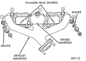
Fig. 51 Intake/Exhaust Manifold Removal/Installation-2.5L EngineCylinder head cover
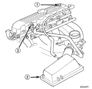
Fig. 52 Engine Cylinder Head Cover
2 - AIR FILTER COVER
3 - FIXED ORIFICE FITTINGRocker arms and push rods
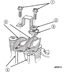
Fig. 53 Rocker Arm Assembly
2 - BRIDGE
3 - PIVOT ASSEMBLY
4 - PUSH RODS
5 - ROCKER ARMS

 Valve spring and seal. Cylinder head. Cylinder head
Other materials:
Adapter/extension housing and
front bearing retainer
DISASSEMBLY
(1) Drain transmission lubricant, if necessary.
(2) Remove release bearing and lever.
(3) Remove clutch housing bolts and remove housing
(Fig. 17).
(4) Remove vehicle speed sensor and speedometer
adapter, if necessary.
(5) Remove bolts holding shift tower to transmission
...