Jeep Cherokee (XJ): Fitting connecting rod bearings. Fitting crankshaft main bearings. Form-in-place gaskets
INSPECTION BEARINGS Inspect the connecting rod bearings for scoring and
bent alignment tabs (Fig. 29) (Fig. 30). Check the
bearings for normal wear patterns, scoring, grooving,
fatigue and pitting (Fig. 31). Replace any bearing
that shows abnormal wear.
Inspect the connecting rod journals for signs of
scoring, nicks and burrs. CONNECTING RODS Misaligned or bent connecting rods can cause
abnormal wear on pistons, piston rings, cylinder
walls, connecting rod bearings and crankshaft connecting
rod journals. If wear patterns or damage to
any of these components indicate the probability of a
misaligned connecting rod, inspect it for correct rod INSPECTION BEARINGS Inspect the connecting rod bearings for scoring and
bent alignment tabs (Fig. 29) (Fig. 30). Check the
bearings for normal wear patterns, scoring, grooving,
fatigue and pitting (Fig. 31). Replace any bearing
that shows abnormal wear.
Inspect the connecting rod journals for signs of
scoring, nicks and burrs. CONNECTING RODS Misaligned or bent connecting rods can cause
abnormal wear on pistons, piston rings, cylinder
walls, connecting rod bearings and crankshaft connecting
rod journals. If wear patterns or damage to
any of these components indicate the probability of a
misaligned connecting rod, inspect it for correct rod alignment. Replace
misaligned, bent or twisted connecting
rods.
1 - UPPER BEARING HALF
1 - ABNORMAL CONTACT AREA CAUSED BY LOCKING TABS
NOT FULLY SEATED OR BEING BENT
BEARING-TO-JOURNAL CLEARANCE (1) Wipe the oil from the connecting rod journal.
(2) Use short rubber hose sections over rod bolts
during installation.
(3) Lubricate the upper bearing insert and install
in connecting rod.
(4) Use piston ring compressor to install the rod
and piston assemblies. The oil squirt holes in the
rods must face the camshaft. The arrow on the piston
crown should point to the front of the engine (Fig.
32). Verify that the oil squirt holes in the rods face
the camshaft and that the arrows on the pistons face
the front of the engine.
(5) Install the lower bearing insert in the bearing
cap. The lower insert must be dry. Place strip of Plastigage
across full width of the lower insert at the center
of bearing cap. Plastigage must not crumble in
use. If brittle, obtain fresh stock.
(6) Install bearing cap and connecting rod on the
journal and tighten nuts to 45 N·m (33 ft. lbs.)
torque. DO NOT rotate crankshaft. Plastigage will
smear, resulting in inaccurate indication.
(7) Remove the bearing cap and determine amount
of bearing-to- journal clearance by measuring the
width of compressed Plastigage (Fig. 33). Refer to
Engine Specifications for the proper clearance. Plastigage
should indicate the same clearance
across the entire width of the insert. If the
clearance varies, it may be caused by either a
tapered journal, bent connecting rod or foreign
material trapped between the insert and cap or
rod.
(8) If the correct clearance is indicated, replacement
of the bearing inserts is not necessary. Remove
the Plastigage from crankshaft journal and bearing
insert. Proceed with installation.
1 - PLASTIGAGE SCALE (9) If bearing-to-journal clearance exceeds the
specification, install a pair of 0.0254 mm (0.001 inch)
undersize bearing inserts. All the odd size inserts
must be on the bottom. The sizes of the service
replacement bearing inserts are stamped on the
backs of the inserts. Measure the clearance as
described in the previous steps.
(10) The clearance is measured with a pair of
0.0254 mm (0.001 inch) undersize bearing inserts
installed. This will determine if two 0.0254 mm
(0.001 inch) undersize inserts or another combination
is needed to provide the correct clearance (refer to
Connecting Rod Bearing Fitting Chart). CONNECTING ROD BEARING FITTING CHART
(11) FOR EXAMPLE: If the initial clearance was
0.0762 mm (0.003 inch), 0.025 mm (0.001 inch)
undersize inserts would reduce the clearance by
0.025 mm (0.001 inch). The clearance would be 0.002
inch and within specification. A 0.051 mm (0.002
inch) undersize insert would reduce the initial clearance
an additional 0.013 mm (0.0005 inch). The
clearance would then be 0.038 mm (0.0015 inch).
(12) Repeat the Plastigage measurement to verify
your bearing selection prior to final assembly.
(13) Once you have selected the proper insert,
install the insert and cap. Tighten the connecting rod
bolts to 45 N·m (33 ft. lbs.) torque. SIDE CLEARANCE MEASUREMENT Slide snug-fitting feeler gauge between the connecting
rod and crankshaft journal flange (Fig. 34).
Refer to Engine Specifications for the proper clearance.
Replace the connecting rod if the side clearance
is not within specification.
FITTING CRANKSHAFT MAIN BEARINGS INSPECTION Wipe the inserts clean and inspect for abnormal
wear patterns and for metal or other foreign material
imbedded in the lining. Normal main bearing insert
wear patterns are illustrated (Fig. 35). In general the
lower bearing half will have a heaver wear pattern.
1 - UPPER INSERT NOTE: If any of the crankshaft journals are scored,
remove the engine for crankshaft repair.
Inspect the back of the inserts for fractures, scrapings
or irregular wear patterns.
Inspect the upper insert locking tabs for damage.
Replace all damaged or worn bearing inserts. FITTING BEARINGS (CRANKSHAFT INSTALLED) The main bearing caps, numbered (front to rear)
from 1 through 7 have an arrow to indicate the forward
position. The upper main bearing inserts are
grooved to provide oil channels while the lower
inserts are smooth.
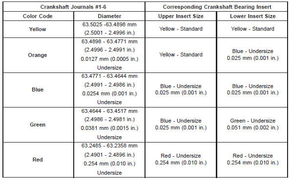
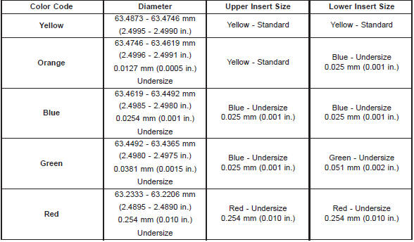
Each bearing insert pair is selectively fitted to its
respective journal to obtain the specified operating
clearance. In production, the select fit is obtained by
using various-sized color-coded bearing insert pairs
as listed in the Main Bearing Fitting Chart. The
bearing color code appears on the edge of the insert.
The size is not stamped on bearing inserts used
for engine production.
The main bearing journal size (diameter) is identified
by a color-coded paint mark (Fig. 36) on the
adjacent cheek or counterweight towards the rear of
the crankshaft (flange end). The rear main journal, is
identified by a color-coded paint mark on the crankshaft
rear flange.
When required, upper and lower bearing inserts of
different sizes may be used as a pair. A standard size
insert is sometimes used in combination with a 0.025
mm (0.001 inch) undersize insert to reduce the clearance
by 0.013 mm (0.0005 inch). Never use a pair
of bearing inserts with greater than a 0.025 mm
(0.001 inch) difference in size. Refer to the
Bearing Insert Pair Chart.
NOTE: When replacing inserts, the odd size inserts
must be either all on the top (in cylinder block) or
all on the bottom (in main bearing cap).
Once the bearings have been properly fitted, proceed
to Crankshaft Main Bearing-Installation. BEARING-TO-JOURNAL CLEARANCE (CRANKSHAFT
INSTALLED) When using Plastigage, check only one bearing
clearance at a time.
Install the grooved main bearings into the cylinder
block and the non-grooved bearings into the bearing
caps.
Install the crankshaft into the upper bearings dry.
Place a strip of Plastigage across full width of the
crankshaft journal to be checked.
Install the bearing cap and tighten the bolts to 108
N·m (80 ft. lbs.) torque.
NOTE: DO NOT rotate the crankshaft. This will
cause the Plastigage to shift, resulting in an inaccurate
reading. Plastigage must not be permitted to
crumble. If brittle, obtain fresh stock.
Remove the bearing cap. Determine the amount of
clearance by measuring the width of the compressed
Plastigage with the scale on the Plastigage envelope (Fig. 37). Refer to Engine
Specifications for the
proper clearance.
1 - NO. 7 MAIN JOURNAL SIZE PAINT MARK BEARING INSERT PAIRS CHART
1 - PLASTIGAGE SCALE Plastigage should indicate the same clearance
across the entire width of the insert. If clearance varies,
it may indicate a tapered journal or foreign
material trapped behind the insert.
If the specified clearance is indicated and there are
no abnormal wear patterns, replacement of the bearing
inserts is not necessary. Remove the Plastigage
from the crankshaft journal and bearing insert. Proceed
to Crankshaft Main Bearing-Installation.
If the clearance exceeds specification, install a pair
of 0.025 mm (0.001 inch) undersize bearing inserts
and measure the clearance as described in the previous
steps.
The clearance indicate with the 0.025 mm (0.001
inch) undersize insert pair installed will determine if
this insert size or some other combination will provide
the specified clearance. FOR EXAMPLE: If the
clearance was 0.0762 mm (0.003 inch) originally, a
pair of 0.0254 mm (0.001 inch) undersize inserts
would reduce the clearance by 0.0254 mm (0.001
inch). The clearance would then be 0.0508 mm (0.002
inch) and within the specification. A 0.051 mm (0.002
inch) undersize bearing insert and a 0.0254 mm
(0.001 inch) undersize insert would reduce the original
clearance an additional 0.0127 mm (0.0005 inch).
The clearance would then be 0.0381 mm (0.0015
inch).
CAUTION: Never use a pair of inserts that differ
more than one bearing size as a pair.
FOR EXAMPLE: DO NOT use a standard size
upper insert and a 0.051 mm (0.002 inch) undersize
lower insert. If the clearance exceeds specification using a pair
of 0.051 mm (0.002 inch) undersize bearing inserts,
measure crankshaft journal diameter with a
micrometer. If the journal diameter is correct, the
crankshaft bore in the cylinder block may be misaligned,
which requires cylinder block replacement or
machining to true bore.
Replace the crankshaft or grind to accept the
appropriate undersize bearing inserts if: Once the proper clearances have been obtained,
proceed to Crankshaft Main Bearing-Installation. MAIN BEARING JOURNAL DIAMETER
(CRANKSHAFT REMOVED) Remove the crankshaft from the cylinder block
(refer to Cylinder Block - Disassemble).
Clean the oil off the main bearing journal.
Determine the maximum diameter of the journal
with a micrometer. Measure at two locations 90
apart at each end of the journal.
The maximum allowable taper and out of round is
0.013 mm (0.0005 inch). Compare the measured
diameter with the journal diameter specification
(Main Bearing Fitting Chart). Select inserts required
to obtain the specified bearing-to-journal clearance.
Install the crankshaft into the cylinder block (refer
to Cylinder Block - Assemble and Crankshaft Main
Bearings - Installation). MAIN BEARING FITTING CHART
There are several places where form-in-place gaskets
are used on the engine. DO NOT use form-inplace
gasket material unless specified. Care
must be taken when applying form-in-place gaskets.
Bead size, continuity and location are of great importance.
Too thin a bead can result in leakage while too
much can result in spill-over. A continuous bead of
the proper width is essential to obtain a leak-free
joint.
Two types of form-in-place gasket materials are
used in the engine area (Mopar Silicone Rubber
Adhesive Sealant and Mopar Gasket Maker). Each
have different properties and cannot be used interchangeably. MOPAR SILICONE RUBBER ADHESIVE SEALANT Mopar Silicone Rubber Adhesive Sealant, normally
black in color, is available in 3 ounce tubes. Moisture
in the air causes the sealant material to cure. This
material is normally used on flexible metal flanges.
It has a shelf life of a year and will not properly cure
if over aged. Always inspect the package for the expiration
date before use. MOPAR GASKET MAKER Mopar Gasket Maker, normally red in color, is
available in 6 cc tubes. This anaerobic type gasket
material cures in the absence of air when squeezed
between smooth machined metallic surfaces. It will
not cure if left in the uncovered tube. DO NOT use
on flexible metal flanges. SURFACE PREPARATION Parts assembled with form-in-place gaskets may be
disassembled without unusual effort. In some
instances, it may be necessary to lightly tap the part
with a mallet or other suitable tool to break the seal
between the mating surfaces. A flat gasket scraper
may also be lightly tapped into the joint but care
must be taken not to damage the mating surfaces.
Scrape or wire brush all gasket surfaces to remove
all loose material. Inspect stamped parts to ensure
gasket rails are flat. Flatten rails with a hammer on
a flat plate, if required. Gasket surfaces must be free
of oil and dirt. Make sure the old gasket material is
removed from blind attaching holes. GASKET APPLICATION Assembling parts using a form-in-place gasket
requires care.
Mopar Silicone Rubber Adhesive Sealant should be
applied in a continuous bead approximately 3 mm
(0.12 inch) in diameter. All mounting holes must be
circled. For corner sealing, a 3 or 6 mm (1/8 or 1/4
inch) drop is placed in the center of the gasket contact area. Uncured sealant
may be removed with a
shop towel. Components should be torqued in place
while the sealant is still wet to the touch (within 10
minutes). The use of a locating dowel is recommended
during assembly to prevent smearing the
material off location.
Mopar Gasket Maker should be applied sparingly
to one gasket surface. The sealant diameter should
be 1.00 mm (0.04 inch) or less. Be certain the material
surrounds each mounting hole. Excess material
can easily be wiped off. Components should be
torqued in place within 15 minutes. The use of a
locating dowel is recommended during assembly to
prevent smearing the material off location.Fitting connecting rod bearings
Fitting crankshaft main bearings
Fig. 29 Connecting Rod Bearing Inspection
2 - MATING EDGES
3 - GROOVES CAUSED BY ROD BOLTS SCRATCHING
JOURNAL DURING INSTALLATION
4 - WEAR PATTERN - ALWAYS GREATER ON UPPER
BEARING
5 - LOWER BEARING HALF
Fig. 30 Locking Tab Inspection
Fig. 31 Scoring Caused by Insufficient Lubrication or by Damaged
Crankshaft Pin Journal
Fig. 32 Rod and Piston Assembly Installation
Fig. 33 Measuring Bearing Clearance with Plastigage
2 - COMPRESSED PLASTIGAGE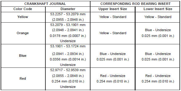
Fig. 34 Checking Connecting Rod Side Clearance- Typical
Fig. 35 Main Bearing Wear Patterns
2 - NO WEAR IN THIS AREA
3 - LOW AREA IN BEARING LINING
4 - LOWER INSERT
Fig. 36 Crankshaft Journal Size Paint I. D. Location
2 - NO. 6 CONNECTING ROD JOURNAL SIZE PAINT MARK
3 - NO. 1 CONNECTING ROD JOURNAL SIZE PAINT MARK
4 - NO. 1 MAIN JOURNAL SIZE PAINT MARK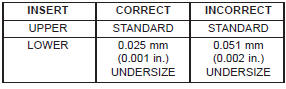
Fig. 37 Measuring Bearing Clearance with
Plastigage
2 - COMPRESSED PLASTIGAGE
Form-in-place gaskets

 Engine performance. Honing cylinder bores. Repair damaged or worn threads
Other materials:
Diagnosis and testing
Power window system
For circuit descriptions and diagrams, refer to
8W-60 - Power Windows in Group 8W - Wiring Diagrams.
ALL WINDOWS INOPERATIVE
(1) Check the circuit breaker in the junction block,
as described in this group. If OK, go to Step 2. If not
OK, replace the faulty circuit breaker.
...