Jeep Cherokee (XJ): Front planetary gear. Sun gear and no. 1 one-way clutch. Second brake
DISASSEMBLY (1) Remove ring gear from planetary gear (Fig. 268).
(2) Remove front bearing and the two races from
ring gear (Fig. 268).
1 - DIRECT CLUTCH (3) Remove tabbed thrust race from planetary gear
(Fig. 268).
(4) Remove snap ring attaching planetary gear to
shaft and remove gear.
1 - FORWARD RACE (5) Remove rear bearing and race from planetary gear.
(6) Measure inside diameter of ring gear bushing.
Maximum allowable diameter is 24.08 mm (0.9480
in.). Replace ring gear if bushing inside diameter is
greater than specified.
(7) Check condition of planetary gear. Replace gear
if teeth are worn, pins are loose, or carrier is cracked,
distorted, or worn. ASSEMBLY (1) Lubricate planetary and ring gear bearings and
races with petroleum jelly.
(2) Identify planetary bearings and races before
installation. (Fig. 268). Bearings and races can be
identified by following dimensions: (3) Install rear race and bearing in gear (Fig. 269).
(4) Turn planetary over and install thrust race
(Fig. 270).
(5) Install front race and bearing and forward race
in ring gear (Fig. 271).
1 - REAR BEARING AND RACE
1 - TABBED THRUST RACE
1 - FRONT BEARING AND RACE
1 - SNAP RING DISASSEMBLY (1) Hold sun gear and turn second brake hub
clockwise and counterclockwise (Fig. 272). Hub
should rotate freely clockwise but lock when turned
counterclockwise. Replace one-way clutch and hub if
they do not operate properly.
(2) Remove one-way clutch/second brake hub
assembly from drum (Fig. 273).
1 - SECOND BRAKE HUB
1 - HUB AND CLUTCH ASSEMBLY (3) Remove thrust washer from drum (Fig. 274).
1 - THRUST WASHER (4) Remove two seal rings from sun gear (Fig.
275).
1 - SEALS RINGS (2) (5) Support sun gear on wood block (Fig. 276).
Then remove first sun gear snap ring and separate
drum from gear.
1 - SUN GEAR (6) Remove remaining snap ring from sun gear
(Fig. 277).
1 - SUN GEAR (7) Measure inside diameter of sun gear bushings
with bore gauge or inside micrometer (Fig. 278).
Maximum allowable diameter is 27.08 mm (1.0661
in.). Replace sun gear if bushing inside diameter is
greater than specified.
1 - BORE GAUGE ASSEMBLY (1) Install first snap ring on sun gear.
(2) Install sun gear in drum and install remaining
snap ring.
(3) Coat replacement seal rings with petroleum
jelly and install them on sun gear. Be sure seal
ring ends are interlocked.
(4) Install thrust washer. Be sure washer tabs are
seated in drum slots.
1 - CLUTCH AND HUB ASSEMBLY (5) Install one-way clutch/second brake hub
assembly on sun gear. Deep side of hub flange faces
upward (Fig. 279).
1 - THRUST WASHER (6) Check one-way clutch operation again (Fig.
272). Hold sun gear and turn second brake hub clockwise
and counterclockwise. Hub should turn clockwise
freely, but lock when turned counterclockwise. DISASSEMBLY (1) Remove second brake drum from output shaft
(Fig. 280).
1 - SECOND BRAKE ASSEMBLY (2) Remove thrust washer from second brake drum
(Fig. 281).
(3) Compress piston return springs with shop
press and tool 7538. Then remove piston snap ring
(Fig. 282).
(4) Remove compressor tool and remove spring
retainer and return springs.
(5) Remove second brake piston and sleeve from
drum with compressed air (Fig. 283). Use only
enough air pressure to ease piston out of drum.
(6) Remove and discard brake piston O-rings.
(7) Measure free length of piston return springs
with springs mounted in retainer (Fig. 284). Length
should be approximately 16.05 mm (0.632 in.).
Replace return springs if length is less than specified.
1 - THRUST WASHER
1 - COMPRESSOR TOOL
1 - PISTON AND SLEEVE
1 - PISTON RETURN SPRINGS ASSEMBLY (1) Lubricate and install new O-rings on brake
piston. Then install brake piston in drum.
(2) Install return springs and retainer on brake
piston.
(3) Compress return springs with shop press and
Compressor Tool 7538. Install piston snap ring and
remove brake assembly from press.
(4) Check brake piston operation with low pressure
compressed air (Fig. 285). Apply air pressure
through feed hole in drum. Piston should move
smoothly when applying-releasing air pressure.
1 - PISTON (5) Coat thrust washer with petroleum jelly and
install it in drum. Be sure washer notches are
aligned with tabs on spring retainer (Fig. 286)
1 - THRUST WASHER NOTCHESFront planetary gear
Fig. 267 Checking Forward Clutch Assembled Height
2 - APPROXIMATELY 71.2 mm (2.80 in.)
3 - FORWARD CLUTCH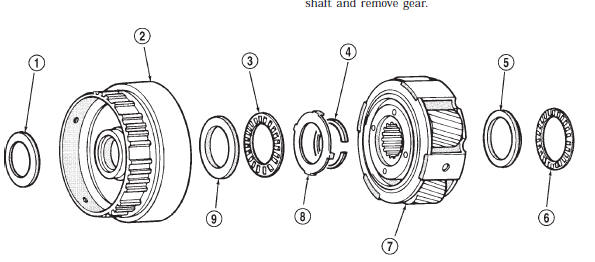
Fig. 268 Front Planetary Gear Components
2 - FRONT PLANETARY RING GEAR
3 - FRONT BEARING
4 - SNAP RING
5 - REAR RACE
6 - REAR BEARING
7 - FRONT PLANETARY GEAR
8 - THRUST RACE
9 - FRONT RACE
Fig. 269 Front Planetary Rear Bearing and Race Installation
2 - PLANETARY GEAR
Fig. 270 Front Planetary Thrust Race Installation
2 - PLANETARY GEAR
Fig. 271 Front Planetary Front Bearing And Races Installation
2 - FORWARD RACESun gear and no. 1 one-way clutch
Sun Gear And One-Way Clutch Components
2 - SUN GEAR
3 - SUN GEAR INPUT DRUM
4 - THRUST WASHER
5 - ONE-WAY CLUTCH AND SECOND BRAKE HUB ASSEMBLY
6 - SNAP RING
7 - SEAL RINGS
Fig. 272 Checking One-Way Clutch Operation
2 - SUN GEAR
Fig. 273 Removing/Installing Brake Hub And Clutch Assembly
2 - DRUM
Fig. 274 Removing/Installing Thrust Washer
Fig. 275 Removing/Installing Sun Gear Seal Rings
Fig. 276 Removing/Installing Sun Gear
2 - SNAP RING
3 - WOOD BLOCK
4 - INPUT DRUM
Fig. 277 Removing/Installing Second Snap Ring
2 - SECOND SNAP RING
Fig. 278 Checking Sun Gear Bushings
Fig. 279 Installing Clutch And Hub Assembly On
Sun Gear
Second Brake Components
2 - SNAP RING
3 - SPRING RETAINER
4 - PISTON RETURN SPRINGS
5 - REAR PLANETARY/OUTPUT SHAFT/FIRST-REVERSE
BRAKE
6 - SECOND BRAKE DRUM
7 - O-RINGS
8 - SECOND BRAKE PISTON
9 - PISTON SLEEVESecond brake
Fig. 280 Removing/Installing Second Brake Assembly
2 - OUTPUT SHAFT
Fig. 281 Removing/Installing Second Brake Drum Thrust Washer
2 - SECOND BRAKE DRUM
Fig. 282 Removing/Installing Second Brake Piston Snap Ring
2 - PISTON SNAP RING
Fig. 283 Removing/Installing Piston And Sleeve
2 - DRUM
Fig. 284 Measuring Second Brake Piston Return Springs
2 - SPRING RETAINER
Fig. 285 Checking Second Brake Piston Operation
2 - DRUM
Fig. 286 Installing Second Brake Thrust Washer
2 - SPRING RETAINER TABS

 Planetary/brake pack/output shaft
Other materials:
Event Data Recorder (EDR)
This vehicle is equipped with an event data recorder
(EDR). The main purpose of an EDR is to record, in
certain crash or near crash-like situations, such as an air
bag deployment or hitting a road obstacle, data that will
assist in understanding how a vehicle's systems performed.
The EDR is d ...