Jeep Cherokee (XJ): Gearshift cable. Brake transmission shift interlock. Transmission valve body solenoids
REMOVAL (1) Shift transmission into Park.
(2) Remove shift lever bezel and necessary console
parts for access to shift lever assembly.
(3) Disconnect cable at shift lever and feed cable
through dash panel opening to underside of vehicle.
(4) Raise vehicle.
(5) Disengage cable eyelet at transmission shift
lever and pull cable adjuster out of mounting
bracket. Then remove old cable from vehicle. INSTALLATION (1) Route cable through hole in dash panel. Fully
seat cable grommet into dash panel.
(2) Place the auto transmission manual shift control
lever in "Park" detent (rearmost) position and
rotate prop shaft to ensure transmission is in park.
(3) Connect shift cable to shifter mechanism by
snapping cable retaining ears into shifter bracket
and press cable end fitting onto lever ball stud.
(4) Place the floor shifter lever in park position.
Ensure that the pawl is seated within the confines of
the adjustment gauge clip.
(5) Snap the cable into the transmission bracket so
the retaining ears are engaged and connect cable end
fitting onto the manual control lever ball stud.
(6) Lock shift cable into position by pushing
upward on the adjusting lock button.
(7) Remove and discard the shift cable adjustment
gauge clip from the park gate of the shifter. REMOVAL (1) Remove lower steering column cover. Refer to
Group 8E, Instrument Panel and Gauges, for proper
procedure.
(2) Remove lower steering column shroud. Refer to
Group 19, Steering, for proper procedure.
(3) Remove tie strap near the solenoid retaining
the brake transmission interlock cable to the steering
column.
(4) Disengage wire connector from solenoid.
(5) With the ignition removed or in the unlocked
position, disengage lock tab holding cable end to
steering column (Fig. 57).
(6) Pull cable end from steering column.
(7) Remove the floor console and related trim.
Refer to Group 23, Body, for proper procedure.
(8) Disconnect the cable eyelet from the bellcrank
(Fig. 58).
(9) Disconnect and remove the cable from the shift
bracket.
1 - IGNITION LOCK INSTALLATION (1) Route replacement cable behind instrument
panel and under floor console area to shift mechanism
(Fig. 58).
(2) Insert cable end into opening in steering column
hub under ignition lock. Push cable inward until lock
tab engages.
(3) Connect the cable end eyelet onto shifter
bellcrank pin.
(4) Place gear selector in PARK.
(5) Push the spring-loaded cable adjuster forward
and snap cable into bracket.
(6) Adjust the brake transmission shifter interlock
cable. Refer to the Adjustment portion of this section
for proper procedures.
(7) Verify that the cable adjuster lock clamp is
pushed downward to the locked position.
(8) Test the park-lock cable operation.
(9) Install the floor console and related trim.
1 - SHIFT MECHANISM (10) Install tie strap to hold cable to base of steering
column.
(11) Install lower steering column shroud and ignition
lock.
(12) Install lower steering column cover. REMOVAL (1) Remove transmission oil pan drain plug and
drain fluid.
(2) Remove pan bolts and remove oil pan.
(3) Remove oil screen bolts and remove screen
(Fig. 59) and gasket. Discard the gasket.
1 - OIL SCREEN BOLTS (4) Disconnect solenoid wire connector (Fig. 60).
(5) If all solenoids are being removed, mark or tag
wires for assembly reference before disconnecting
them.
(6) Remove bolt attaching solenoids to valve body
and remove solenoids (Fig. 61). Do not allow any
valve body components to fall out when solenoids are
removed.
(7) Clean oil filter and pan with solvent and dry
with compressed air.
(8) Remove old sealer material from oil pan and
transmission case. INSTALLATION (1) Position solenoids on valve body and install
solenoid bolts. Tighten bolts to 10 N·m (7 ft. lbs.)
torque.
(2) Connect feed wires to solenoids.
(3) Install new gaskets on oil screen and install
screen. Tighten screen bolts to 10 N·m (7 ft. lbs.)
torque.
1 - SOLENOID WIRE CONNECTORS
1 - VALVE BODY SOLENOIDS (4) Apply bead of Threeebondt Liquid Gasket
TB1281, P/N 83504038, sealer to oil pan sealing surface.
Sealer bead should be at least 3.0 mm (1/8 in.)
wide.
(5) Install oil pan on transmission. Tighten pan
bolts to 7 N·m (65 in. lbs.) torque.
(6) Install and tighten oil pan drain plug to 20
N·m (15 ft. lbs.) torque.
(7) Fill transmission with Mopart Dexron IIE/Mercon.Gearshift cable
Brake transmission shift interlock
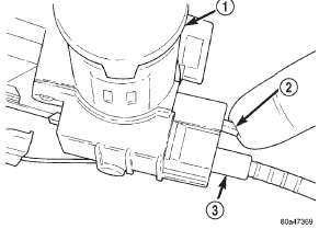
Fig. 57 Brake/Park Interlock Cable
2 - LOCK TAB
3 - CABLE END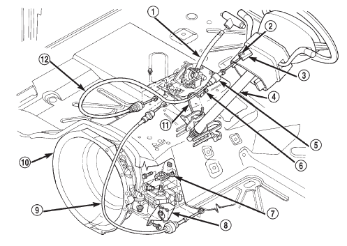
Fig. 58 Cable and Shifter
2 - LOCK-TAB
3 - IGNITION LOCK INTERLOCK
4 - STEERING COLUMN
5 - SOLENOID
6 - WIRE CONNECTOR
7 - LEVER
8 - MOUNT BRACKET
9 - SHIFT CABLE
10 - AUTOMATIC TRANSMISSION
11 - TIE STRAP
12 - PARK/BRAKE INTERLOCK CABLETransmission valve body solenoids
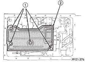
Fig. 59 Oil Screen Removal/Installation
2 - OIL SCREEN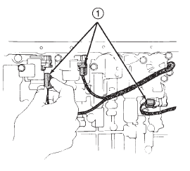
Fig. 60 Solenoid Wire Connectors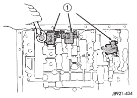
Fig. 61 Transmission Valve Body Solenoids
 Speedometer adapter. Speed sensor rotor-speedometer
drive gear. Park/neutral position switch
Speedometer adapter. Speed sensor rotor-speedometer
drive gear. Park/neutral position switch
 Transmission valve body. Transmission control module. Solenoid harness adapter seal
Other materials:
Removal and installation
Combination flasher
WARNING: ON VEHICLES EQUIPPED WITH AIRBAGS,
REFER TO GROUP 8M - PASSIVE
RESTRAINT SYSTEMS BEFORE ATTEMPTING ANY
STEERING WHEEL, STEERING COLUMN, OR
INSTRUMENT PANEL COMPONENT DIAGNOSIS OR
SERVICE. FAILURE TO TAKE THE PROPER PRECAUTIONS
COULD RESULT IN ACCIDENTAL AIRBAG
DEP ...