Jeep Cherokee (XJ): Gearshift mechanism. Converter drainback valve. Brake transmission shift interlock mechanism
DESCRIPTION The shift mechanism is cable operated and provides
six shift positions. The shift indicator is located
on the console next to the gear shift. The shift positions
are: OPERATION Manual low (1) range provides first gear only. Over
run braking is also provided in this range. Manual
second (2) range provides first and second gear only.
1 - SEAL RING (PLAIN END) Drive range provides first, second, and third gear
ranges. DESCRIPTION The drainback valve is located in the transmission
cooler outlet (pressure) line. OPERATION The valve prevents fluid from draining from the
converter into the cooler and lines when the vehicle
is shut down for lengthy periods. Production valves
have a hose nipple at one end, while the opposite end
is threaded for a flare fitting. All valves have an
arrow (or similar mark) to indicate direction of flow
through the valve. DESCRIPTION The Brake Transmission Shifter/Ignition Interlock
(BTSI), is a cable and solenoid operated system. It
interconnects the automatic transmission floor
mounted shifter to the steering column ignition
switch (Fig. 54). OPERATION The system locks the shifter into the PARK position.
The Interlock system is engaged whenever the
ignition switch is in the LOCK or ACCESSORY position.
An additional electrically activated feature will
prevent shifting out of the PARK position unless the
brake pedal is depressed at least one-half an inch. A
magnetic holding device in line with the park/brake
interlock cable is energized when the ignition is in the RUN position. When the
key is in the RUN position
and the brake pedal is depressed, the shifter is
unlocked and will move into any position. The interlock
system also prevents the ignition switch from
being turned to the LOCK or ACCESSORY position
(Fig. 55) unless the shifter is fully locked into the
PARK position.
1 - GOVERNOR PRESSURE
Gearshift mechanism
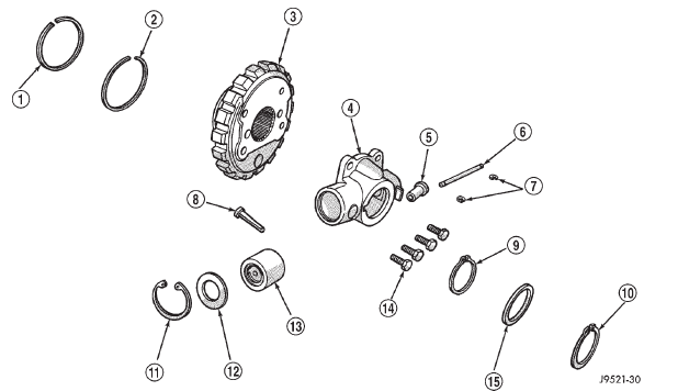
Fig. 50 Governor
2 - SEAL RING (HOOK END)
3 - PARK GEAR
4 - GOVERNOR BODY
5 - GOVERNOR VALVE
6 - VALVE SHAFT
7 - E-CLIPS (2)
8 - FILTER
9 - SNAP RING (THIN)
10 - SNAP RING (THICK)
11 - SNAP RING
12 - RETAINER WASHER
13 - GOVERNOR WEIGHT ASSEMBLY
14 - GOVERNOR BODY BOLTS (4)
15 - WASHERConverter drainback valve
Brake transmission shift interlock
mechanism
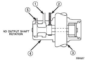
Fig. 51 Governor-No Output Shaft Rotation
2 - LINE PRESSURE
3 - OUTPUT SHAFT
4 - GOVERNOR
5 - VENT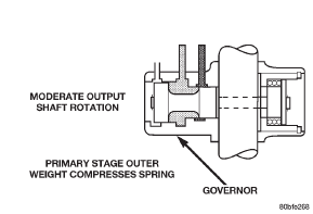
Fig. 52 Governor-Moderate Output Shaft Rotation


Other materials:
Before You Begin Programming HomeLink. Programming A Rolling Code. Programming A Non-Rolling Code
Before You Begin Programming HomeLink
Ensure your vehicle is parked outside of the garage
before you begin programming.
For more efficient programming and accurate transmission
of the radio-frequency signal it is recommended that
a new battery be placed in the hand-held transmitter of
the dev ...