Jeep Cherokee (XJ): General information. Description and operation. Diagnosis and testing
INTRODUCTION Individually controlled electrically heated front
seats are available factory-installed optional equipment
on this model. The seat heaters will only operate
when the ignition switch is in the ON position,
and the surface temperature at the front seat heating
element sensors is below the designed temperature
set points of the system. The heated seat system will
not operate in ambient temperatures greater than
about 32 C (90 F).
There are separate momentary, tactile, two-directional
rocker switches located in the center console
with center NEUTRAL, HI and LO positions for each
front seat. Depressing the rocker switch to its
momentary HI or LO position signals the Seat Heat
Interface Module (SHIM) to power the selected
heated seat and maintain the requested temperature
setting (HI or LO). Each switch has a HI and LO
Light-Emitting Diode (LED) which, via the SHIM,
illuminates to give a visual indication that the system
is in the HI or LO mode. The LO heat set point
is about 32 C (90 F), and the HI heat set point is
about 38 C (100 F). The system shall be deactivated
whenever the same set position is depressed a second
time and shall change states directly when switching
from HI to LO or vice versa. The system shall be
deactivated whenever the ignition switch is placed in
the off position. When the ignition switch is placed
back in the run position, the heated seat system
shall remain deactivated until a momentary switch is
depressed. When a seat heater is turned on, a sensor
located near the seat cushion electric heater element
provides the SHIM with input indicating the surface
temperature of the seat cushion. If the surface temperature
input is below the temperature set point of
the SHIM for the selected temperature setting, an
N-FET Transistor within the SHIM energizes the
heating elements in the seat cushion and back. When
the sensor input indicates the correct temperature
set point has been achieved, the SHIM de-energizes
the N-FET. The SHIM will continue to cycle the
N-FET as needed to maintain the temperature set
point.
The SHIM will automatically turn off the heating
elements if it detects a short or an open in the heating
element or a sensor out of range. These conditions
will also cause the SHIM to notify the occupant
of the failure via flashing the heated seat switch
LED's as discussed later.
Switched battery power to the SHIM is supplied by
the heated seat relay mounted to the seat cushion
frame with the SHIM under the right front seat. The
battery feed is protected by a circuit breaker located
in the junction block.
Following are general descriptions of the major
components in the heated seat system. Refer to
8W-63 - Power Seat With Heated Seats in Group 8W
- Wiring Diagrams for complete circuit descriptions
and diagrams. The heated seat switch assembly is located on the
center console where the ashtray is normally located
(Fig. 1). The two momentary, two-directional rocker
switches, one switch for each front seat, provide a
resistor-multiplexed signal to the Seat Heat Interface
Module (SHIM). Each switch has center NEUTRAL,
and momentary LO and HI positions so that both the
driver and the front seat passenger can select a preferred
seat heating mode.
Each switch has two telltales (LED's) which indicate
the mode of the heater of the respective seat.
1 - ASH RECEIVER The switches also have LED's which provide backlighting
when the ignition switch is in the ON position.
The LED's cannot be repaired. If the LED is
faulty, the individual switch must be replaced. The Seat Heat Interface Module (SHIM) is an electronic
microprocessor controlled device designed to
operate the electric seat heater elements. The SHIM
is located under the right front seat cushion. Inputs
to the module include the console mounted resistor
multiplexed switch signals, seat cushion temperature
sensors, a relay-switched battery feed, and a ground.
The SHIM outputs are the feed for the seat heating
elements and sensors, and the switch telltale circuits.
The SHIM cannot be repaired and, if faulty or damaged,
it must be replaced. Heated seat relay The heated seat relay is located under the right
front seat cushion near the SHIM. Ignition and battery
power is fed to the relay, which then provides a
switched battery feed to the SHIM. The heated seat
relay cannot be repaired and, if faulty or damaged, it
must be replaced. Two heated seat heating elements are used in each
front seat, one for the seat cushion and the other for
the seat back. The two elements for each seat are
connected in series with the SHIM.
The temperature sensor is a Negative Temperature
Coefficient (NTC) thermistor. One temperature sensor
is used for each seat, and it is integral to the seat
cushion heating element.
The heating elements are sewn into the seat cushion
cover and seat back cover assemblies, which are
serviced individually. The heating elements and temperature
sensor cannot be repaired and, if faulty or
damaged, the affected seat cover assembly must be
replaced. Refer to Group 23 - Body for the seat cushion
cover and seat back cover Removal and Installation. For circuit descriptions and diagrams, refer to 8W -
63 - Power Seat With Heated Seats in Group 8W -
Wiring Diagrams.
WARNING: ON VEHICLES EQUIPPED WITH AIRBAGS,
REFER TO GROUP 8M - PASSIVE
RESTRAINT SYSTEMS BEFORE ATTEMPTING ANY
STEERING WHEEL, STEERING COLUMN, OR
INSTRUMENT PANEL COMPONENT DIAGNOSIS OR
SERVICE. FAILURE TO TAKE THE PROPER PRECAUTIONS
COULD RESULT IN ACCIDENTAL AIRBAG
DEPLOYMENT AND POSSIBLE PERSONAL
INJURY.
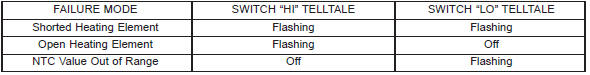
The heated seat system is capable of performing
some self-diagnostics. The following table depicts the
various failure modes which will be reported to the
occupant via flashing the momentary switch telltales.
The switch telltales will flash on the driver's switch
if the failure exists in the driver's seat portion of the
system, similarly with the passenger's switch. The
telltale will illuminate for approximately a 1⁄2second
on, 1⁄2second off pulse for a duration of one minute.
This process will repeat every time the system is initiated
via the switches until the problem has been
corrected. SEAT HEAT INTERFACE MODULE DIAGNOSTIC ROUTINES
Before testing the individual components in the
heated seat system, check the following: For circuit descriptions and diagrams, refer to 8W -
63 - Power Seat With Heated Seats in Group 8W -
Wiring Diagrams.
WARNING: ON VEHICLES EQUIPPED WITH AIRBAGS,
REFER TO GROUP 8M - PASSIVE
RESTRAINT SYSTEMS BEFORE ATTEMPTING ANY
STEERING WHEEL, STEERING COLUMN, OR
INSTRUMENT PANEL COMPONENT DIAGNOSIS OR
SERVICE. FAILURE TO TAKE THE PROPER PRECAUTIONS
COULD RESULT IN ACCIDENTAL AIRBAG
DEPLOYMENT AND POSSIBLE PERSONAL
INJURY. BACKLIGHTING (1) Disconnect and isolate the battery negative
cable
(2) Remove the heated seat switch assembly from
the center console. Remove the connector from the
suspect switch. Check for continuity between the
ground circuit cavity of the 6-way heated seat switch
wire harness connector and a good ground. There
should be continuity. If OK, go to Step 3. If not OK,
repair the open circuit as required.
(3) Connect the battery negative cable. Turn the
ignition switch to the ON position. Check for battery
voltage at the fused ignition switch output circuit
cavity of the 6-way heated seat switch wire harness
connector. If OK, turn the ignition switch to the OFF
position, disconnect and isolate the battery negative
cable, and replace the heated seat switch. If not OK,
repair the open circuit as required. TELLTALES (1) Replace the heated seat switch with a known
good unit and test the operation of the switch telltales.
If OK, discard the faulty heated seat switch. If
not OK, see Seat Heat Interface Module in the Diagnosis
and Testing section of this group. MULTIPLEXED RESISTANCES (1) Disconnect and isolate the battery negative
cable.
(2) Remove the heated seat switch assembly from
the center console. Remove the connector from the
suspect switch.
(3) With the suspect heated seat switch in the
NEUTRAL position, using an ohmmeter, measure the
resistance between the fused ignition switch output
circuit terminal and the heated seat switch output
circuit terminal in the 6-way connector receptacle on
the back of the switch. The resistance reading should
be about 2.2. Kohms. If OK, go to Step 4. If not OK,
replace the faulty switch.
(4) Hold the suspect heated seat switch in the LO
position. Using an ohmmeter, check the resistance
between the fused ignition switch output circuit terminal
and the heated seat switch output circuit terminal
in the 6-way connector receptacle on the back
of the switch. The resistance reading should be about
414 Ohms. If OK, go to Step 5. If not OK, replace the
faulty switch.
(5) Hold the suspect heated seat switch in the HI
position. Using an ohmmeter, check the resistance
between the fused ignition switch output circuit terminal
and the heated seat switch output circuit terminal
in the 6-way connector receptacle on the back of the switch. The resistance
reading should be about
32.5 Ohms. If OK, see Heated Seat Relay in the
Diagnosis and Testing section of this group. If not
OK, replace the faulty switch. The wire harness connectors for the seat cushion
and seat back heating elements are located under the
seat, near the rear edge of the seat cushion frame.
For circuit descriptions and diagrams, refer to 8W -
63 - Power Seat With Heated Seats in Group 8W -
Wiring Diagrams.
SEAT CUSHION
(1) Disconnect and isolate the battery negative
cable. Unplug the 4-way heated seat cushion wire
harness connector.
(2) Check for continuity between the two heated
seat element circuit cavities of the seat cushion cover
half of the heated seat cushion wire harness connector.
There should be continuity. If OK, go to Step 3. If
not OK, replace the faulty seat cushion cover.
(3) Check for continuity between one of the heated
seat element circuit cavities of the seat cushion cover
half of the heated seat cushion wire harness connector
and the seat cushion frame. There should be no
continuity. If OK, see Seat Back in the Diagnosis and
Testing section of this group. If not OK, replace the
faulty seat cushion cover. SEAT BACK (1) Disconnect and isolate the battery negative
cable. Unplug the 2-way heated seat back wire harness
connector.
(2) Check for continuity between the heated seat
element circuit cavity and the ground circuit cavity of
the seat back cover half of the heated seat back wire
harness connector. There should be continuity. If OK,
go to Step 3. If not OK, replace the faulty seat back
cover.
(3) Check for continuity between the heated seat
element circuit cavity of the seat back cover half of
the heated seat back wire harness connector and the
seat back frame. There should be no continuity. If
OK, see Heated Seat Sensor in the Diagnosis and
Testing section of this group. If not OK, replace the
faulty seat back cover. HEATED SEAT SENSOR The wire harness connector for the seat cushion
heating element and sensor are located under the
seat, near the rear edge of the seat cushion frame.
For circuit descriptions and diagrams, refer to 8W -
63 - Power Seat With Heated Seats in Group 8W -
Wiring Diagrams.
(1) Disconnect and isolate the battery negative
cable. Unplug the 4-way heated seat cushion wire
harness connector.
(2) Using an ohmmeter, check the resistance
between the heated seat sensor input circuit cavity
and the heated seat sensor feed circuit cavity of the
seat cushion cover half of the heated seat cushion
wire harness connector. The sensor resistance should
be between 1 Kohm and 200 Kohms. If OK, see
Heated Seat Relay in the Diagnosis and Testing section
of this group. If not OK, replace the faulty seat
cushion cover. For circuit descriptions and diagrams, refer to 8W -
63 - Power Seat With Heated Seats in Group 8W -
Wiring Diagrams.
(1) Disconnect and isolate the battery negative
cable. Unplug the 8-way heated seat relay connector.
(2) Check for continuity between the ground circuit
cavity of the 8-way heated seat relay wire harness
connector and a good ground. There should be
continuity. If OK, go to Step 3. If not OK, repair the
open circuit as required.
(3) Connect the battery negative cable. Check for
battery voltage at the battery feed circuit cavity (pin
8) of the 8-way heated seat relay wire harness connector.
If OK, go to Step 4. If not OK, repair the open
circuit as required.
(4) Turn the ignition switch to the ON position.
Check for battery voltage at the fused ignition switch
output circuit cavity of the 8-way heated seat relay
wire harness connector. If OK, turn the ignition
switch to the OFF position, disconnect and isolate
the battery negative cable, and go to Step 5. If not
OK, repair the open circuit as required.
(5) Unplug the 14-way seat heat interface module
(SHIM) connector. Check for continuity between the
two switched battery feed cavities of the 14-way
SHIM wire harness connector and the switched battery
feed cavity of the 8-way heated seat relay wire
harness connector. If OK, reconnect the heated seat
relay wire harness connector, and go to Step 6. If not
OK, repair the open circuit as required.
(6) Connect the battery negative cable. Turn the
ignition switch to the ON position. Check for battery
voltage at the switched battery feed cavities of the
14-way SHIM wire harness connector. If OK, turn
the ignition switch to the OFF position, disconnect
and isolate the battery negative cable, and see Seat
Heat Interface Module in the diagnosis and testing
section of this group. If not OK, replace the heated
seat relay. Before testing the seat heat interface module, test
the heated seat switch, the heated seat elements, and
the heated seat sensor as described in the Diagnosis
and Testing section of this group. If testing of the
heated seat switch, elements, and sensor reveals no
problems, proceed as follows. For circuit descriptions
and diagrams, refer to 8W - 63 - Power Seat With
Heated Seats in Group 8W - Wiring Diagrams.
(1) Replace the seat heat interface module with a
known good unit and test the operation of the heated
seats. If OK, discard the faulty seat heat interface
module. If not OK, go to Step 2.
(2) Test each of the circuits from the heated seat
switch, heated seat relay, heated seat elements, and
heated seat sensor to the seat heat interface module.
Repair any short or open circuits as required.General information
Description and operation
Heated seat switch
Fig. 1 Heated Seat Switch Location
2 - HEATED SEAT SWITCHES & BEZEL
3 - WIRE HARNESS CONNECTORS
4 - FLOOR CONSOLESeat heat interface module
Heated seat element and sensor
Diagnosis and testing
Heated seat system
Heated seat switch
Heated seat element and sensor
Heated seat relay
Seat heat interface module


Other materials:
Reporting safety defects
In The 50 United States And Washington, D.C.
If you believe that your vehicle has a defect that could
cause a crash or cause injury or death, you should
immediately inform the National Highway Traffic Safety
Administration (NHTSA) in addition to notifying the
manufacturer.
If NHTSA receives si ...