Jeep Cherokee (XJ): Overrunning clutch/low-reverse drum. Front servo piston. Rear servo piston
DISASSEMBLY (1) If the clutch assembly came out with the lowreverse
drum, thread two clutch cam bolts into the
cam. Then lift the cam out of the drum with the bolts
(Fig. 164). Rotate the cam back and forth to ease
removal if necessary.
1 - CAM BOLTS (2) Remove the clutch roller and spring assembly
from the overrunning clutch race. ASSEMBLY (1) Assemble clutch rollers and springs in retainer
if necessary (Fig. 165).
(2) Install overrunning clutch roller, spring and
retainer assembly in clutch cam (Fig. 166).
(3) Temporarily assemble and check overrunning
clutch operation as follows:
(a) Assemble cam and clutch.
1 - RETAINER
1 - CLUTCH CAM
2 - CLUTCH ROLL ASSEMBLY (b) Install clutch assembly on low-reverse drum
with twisting motion (Fig. 167).
(c) Install drum-clutch assembly in case and
install clutch cam bolts.
(d) Install rear support and support attaching
bolts.
(e) Check low-reverse drum rotation. Drum
should rotate freely in clockwise direction
and lock when turned in counterclockwise
direction (as viewed from front of case).
1 - LOW-REVERSE DRUM DISASSEMBLY (1) Remove seal ring from rod guide (Fig. 169).
(2) Remove small snap ring from servo piston rod.
Then remove piston rod, spring and washer from piston.
(3) Remove and discard servo component O-ring
and seal rings. ASSEMBLY (1) Lubricate new O-ring and seal rings with
petroleum jelly and install them on piston, guide and
rod.
(2) Install rod in piston. Install spring and washer
on rod. Compress spring and install snap ring (Fig.
169).
(3) Set servo components aside for installation during
transmission reassembly.
1 - LOW-REVERSE DRUM
1 - PISTON RINGS DISASSEMBLY (1) Remove small snap ring and remove plug and
spring from servo piston (Fig. 170).
(2) Remove and discard servo piston seal ring. ASSEMBLY (1) Lubricate piston and guide seals with petroleum
jelly. Lubricate other servo parts with Mopart
ATF Plus 3, Type 7176, transmission fluid.
(2) Install new seal ring on servo piston.
(3) Assemble piston, plug, spring and new snap
ring.
(4) Lubricate piston seal lip with petroleum jelly.
1 - SNAP RINGOverrunning clutch/low-reverse
drum

Fig. 164 Removing Overrunning Clutch From Low-Reverse Drum
2 - LOW-REVERSE DRUM>
3 - OVERRUNNING CLUTCH AND CAM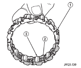
Fig. 165 Overrunning Clutch Rollers, Springs, Retainer
2 - SPRING
3 - ROLLER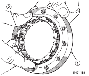
Fig. 166 Assembling Overrunning Clutch And Cam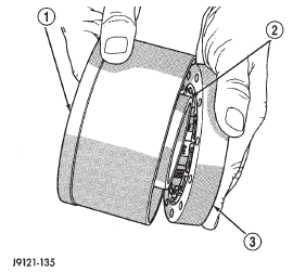
Fig. 167 Temporary Assembly Of Clutch And Drum To Check Operation
2 - CLUTCH RACE (ON HUB OF DRUM)
3 - OVERRUNNING CLUTCHFront servo piston
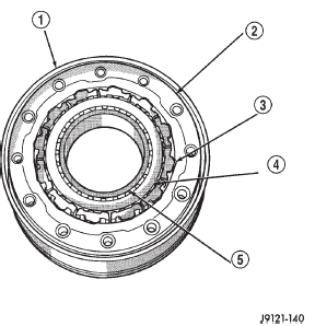
Fig. 168 Assembled Overrunning Clutch
2 - OVERRUNNING CLUTCH CAM
3 - ROLLER AND SPRING ASSEMBLY
4 - CLUTCH RACE
5 - HUB OF LOW-REVERSE DRUM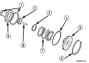
Fig. 169 Front Servo
2 - O-RING
3 - SNAP-RING
4 - SEAL RING
5 - PISTON ROD GUIDE
6 - SNAP-RING
7 - SERVO SPRING
8 - PISTON ROD
9 - SERVO PISTONRear servo piston
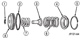
Fig. 170 Rear Servo Components
2 - PISTON SEAL
3 - PISTON PLUG
4 - SPRING RETAINER
5 - SNAP RING
6 - PISTON SPRING
7 - CUSHION SPRING
8 - PISTON
 Governor and park gear. Valve body. Transmission
 Oil pump and reaction shaft support
Other materials:
Diagnosis and testing
General diagnosis information
Shift points are controlled by the transmission control
module (TCM). Before attempting repair, determine
if a malfunction is electrical or mechanical.
The TCM used with the AW-4 transmission has a
self-diagnostic program compatible with the DRBIII
scan tool. The ...