Jeep Cherokee (XJ): Rear suspension
The rear suspension is comprised of: CAUTION: A vehicle should always be loaded so
the vehicle weight center-line is located immediately
forward of the rear axle. Correct vehicle loading
provides proper front tire-to-road contact. This
results in maximum vehicle handling stability and
safety. Incorrect vehicle weight distribution can
cause excessive tire tread wear, spring fatigue or
failure, and erratic steering.
CAUTION: Suspension components with rubber/
urethane bushings (except stabilizer bar) should be
tightened with the vehicle at normal ride height. It is
important to have the springs supporting the weight
of the vehicle when the fasteners are torqued. If
springs are not at their normal ride position, vehicle
ride comfort could be affected and premature bushing
wear may occur. DESCRIPTION The top of the shock absorbers are bolted to the
body crossmember. The bottom of the shocks are
bolted to the axle brackets. OPERATION The shock absorbers dampen jounce and rebound
motion of the vehicle over various road conditions
and limit suspension rebound travel. DESCRIPTION The jounce bumpers are bolted to the bottom of the
frame rail. OPERATION The jounce bumpers are used to limit suspension
travel in compression. DESCRIPTION The spring steel bar extends across the axle and
mounts to leaf spring brackets. Links are connected
from the bar to the underside of the frame rail. The
stabilizer bar and links are isolated by rubber bushings. OPERATION The stabilizer bar is used to control vehicle body
roll during turns. The bar helps to control the vehicle
body in relationship to the suspension. DESCRIPTION The front of the multi-leaf springs mount to frame
rail brackets. The rear of the spring mounts to shackles
which mount the frame. The springs and shackles
have bushing at the mounting points. OPERATION The leaf springs control ride quality and maintain
proper ride height. The shackles allow the springs to
change their length as the vehicle moves over various
road conditions. The bushings are used to isolate
axle/road noise. SPRING AND SHOCK A knocking or rattling noise from a shock absorber
may be caused by movement between mounting
bushings and metal brackets or attaching components.
These noises can usually be stopped by tightening
the attaching nuts. If the noise persists,
inspect for damaged and worn bushings, and attaching
components. Repair as necessary if any of these
conditions exist.
A squeaking noise from the shock absorber may be
caused by the hydraulic valving and may be intermittent.
This condition is not repairable and the shock
absorber must be replaced.
The shock absorbers are not refillable or adjustable.
If a malfunction occurs, the shock absorber
must be replaced. To test a shock absorber, hold it in
an upright position and force the piston in and out of
the cylinder four or five times. The action throughout
each stroke should be smooth and even.
The spring eye and shock absorber bushings do not
require any type of lubrication. Do not attempt to
stop spring bushing noise by lubricating them.
Grease and mineral oil-base lubricants will deteriorate
the bushing rubber.
If the vehicle is used for severe, off-road operation,
the springs should be examined periodically. Check
for broken and shifted leafs, loose and missing clips,
and broken center bolts. Refer to Spring and Shock
Absorber Diagnosis chart for additional information. SPRING AND SHOCK ABSORBER CONDITION POSSIBLE CAUSES CORRECTION REMOVAL INSTALLATION REMOVAL INSTALLATION REMOVAL AND INSTALLATION
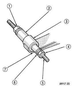
1 - SHOCK ABSORBER REMOVAL INSTALLATION For front bushings bend tabs DOWN before
removal. Use an appropriate driver tool and force the
original bushing out of the spring eye.
1 - LINK
1 - NUT TORQUE CHART DESCRIPTION TORQUE Shock Absorber Upper Bolt . . . . . . . . . . . . . . . 23 N·m (17 ft. lbs.) Stabilizer Bar Clamp Bolt . . . . . . . . . . . . . . . 54 N·m (40 ft. lbs.) Spring U-Bolt Nut . . . . . . . . . . . . . . . 70 N·m (52 ft. lbs.)Description and operation
Suspension component
Shock absorbers
Jounce bumpers
Stabilizer bar
Coil springs and isolators
Diagnosis and testing
SPRING SAGS
SPRING NOISE
SHOCK NOISE
Removal and installation
Shock absorber
Stabilizer bar

Fig. 1 Rear Suspension Components
2 - SPRING BRACKET
3 - NUT
4 - BUSHING
5 - BUMPER
6 - BRACKET
7 - NUT
8 - RETAINER
9 - SHOCK ABSORBER
10 - SPRING
11 - U-BOLTS
12 - BUSHING
13 - SHACKLELeaf spring
Leaf spring and shackle bushing

Fig. 2 Stabilizer Bar
2 - BUSHING
3 - GROMMET
4 - FRAME RAIL
5 - CLAMP
6 - SCREW
7 - NUT
8 - SPRING BRACKET
9 - BOLT
10 - SWAY BAR
11 - SCREW

Fig. 3 Spring Eye Bushing Removal
2 - PIPE
(RECEIVER)
3 - SPRING EYE
4 - NUT
5 - THREADED ROD
6 - FLAT WASHER
7 - SOCKET WRENCH
(DRIVER)Specifications
Lower Nut . . . . . . . . . . . . . . . 62 N·m (46 ft. lbs.)
Link Upper Bolt . . . . . . . . . . . 12 N·m (9 ft. lbs.)
Link Lower Nut . . . . . . . . . . . 74 N·m (55 ft. lbs.)
Front Pivot Bolt . . . . . . . . . 156 N·m (115 ft. lbs.)
Upper Shackle Bolt . . . . . . 156 N·m (115 ft. lbs.)
Lower Shackle Bolt . . . . . . . 108 N·m (80 ft. lbs.)
Other materials:
Axle shaft. Axle shaft seal and bearing. Differential
Axle shaft
REMOVAL
(1) Raise and support vehicle. Ensure that the
transmission is in neutral.
(2) Remove wheel and tire assembly.
(3) Remove brake drum. Refer to Group 5, Brakes,
for proper procedure.
(4) Clean all foreign material from housing cover
area.
(5) Loosen housing cover bo ...


