Jeep Cherokee (XJ): Removal and installation
Both the battery negative cable and the battery
positive cable are serviced in the battery wire harness.
If either battery cable is damaged or faulty, the
battery wire harness unit must be replaced. REMOVAL (1) Turn the ignition switch to the Off position. Be
certain that all electrical accessories are turned off.
(2) Loosen the battery negative cable terminal
clamp pinch-bolt hex nut.
(3) Disconnect the battery negative cable terminal
clamp from the battery negative terminal post. If
necessary, use a battery terminal puller to remove
the terminal clamp from the battery post.
(4) Loosen the battery positive cable terminal
clamp pinch-bolt hex nut.
(5) Disconnect the battery positive cable terminal
clamp from the battery positive terminal post. If necessary,
use a battery terminal puller to remove the
terminal clamp from the battery post.
(6) Unlatch and remove the B(+) terminal stud
cover from the front of the Power Distribution Center
(PDC).
(7) Remove the nut that secures the battery positive
cable eyelet terminal and the generator output
cable eyelet terminal to the B(+) terminal stud on the
PDC.
(8) Remove the battery positive cable eyelet terminal
and the generator output cable eyelet terminal
from the B(+) terminal stud on the PDC.
(9) Disconnect the battery wire harness connector
from the headlamp and dash wire harness connector
located below the front of the PDC. (10) Remove the screw that secures the battery
negative cable eyelet terminal to the inner fender
shield near the battery.
(11) On LHD models with air conditioning, disconnect
the compressor clutch wire harness connector
from the battery wire harness connector.
(12) Unlatch and remove the cover from the generator
output terminal stud housing on the back of the
generator.
(13) Remove the nut that secures the generator
output cable eyelet terminal to the generator output
terminal stud.
(14) Remove the generator output cable eyelet terminal
from the generator output terminal stud.
(15) Disconnect the battery wire harness connector
from the generator field terminal connector receptacle
on the back of the generator.
(16) Remove the nut that secures the battery negative
cable ground eyelet terminal to the stud on the
right side of the engine block.
(17) Remove the battery negative cable ground
eyelet terminal from the engine block stud.
(18) On models with a 2.5L engine, remove the nut
that secures the battery wire harness locator clip to
the stud on the right side engine block oil pan rail
below and forward of the engine oil filter adapter.
(19) On models with a 4.0L engine, remove the
screw that secures the battery wire harness locator
clip to the right side of the engine block between and
below the right engine mount and the oil filter
adapter.
(20) Remove the nut that secures the battery positive
cable eyelet terminal to the B(+) terminal stud
on the starter solenoid.
(21) Remove the battery positive cable eyelet terminal
from the B(+) terminal stud on the starter
solenoid.
(22) Disconnect the battery wire harness connector
from the connector receptacle on the starter solenoid.
(23) Remove the battery wire harness from the
engine compartment. INSTALLATION (1) Clean and inspect the battery cable terminal
clamps and the battery terminal posts. Refer to Battery
in the index of this service manual for the location
of the proper battery cable terminal clamp and
battery terminal post cleaning and inspection procedures.
(2) Position the battery wire harness into the
engine compartment.
(3) Reconnect the battery wire harness connector
to the connector receptacle on the starter solenoid.
(4) Install the battery positive cable eyelet terminal
onto the B(+) terminal stud on the starter solenoid.
(5) Install and tighten the nut that secures the
battery positive cable eyelet terminal to the B(+) terminal
stud on the starter solenoid. Tighten the nut to
10 N·m (90 in. lbs.).
(6) On models with a 2.5L engine, install and
tighten the nut that secures the battery wire harness
locator clip to the stud on the right side engine block
oil pan rail below and forward of the engine oil filter
adapter. Tighten the nut to 8.4 N·m (75 in. lbs.).
(7) On models with a 4.0L engine, install and
tighten the screw that secures the battery wire harness
locator clip to the right side of the engine block
between and below the right engine mount and the
oil filter adapter. Tighten the screw to 8.4 N·m (75 in.
lbs.).
(8) Install the battery negative cable ground eyelet
terminal onto the stud on the right side of the engine
block.
(9) Install and tighten the nut that secures the
battery negative cable ground eyelet terminal to the
stud on the right side of the engine block. Tighten
the nut to 15.8 N·m (140 in. lbs.).
(10) Reconnect the battery wire harness connector
to the generator field terminal connector receptacle
on the back of the generator.
(11) Install the generator output cable eyelet terminal
onto the generator output terminal stud.
(12) Install and tighten the nut that secures the
generator output cable eyelet terminal to the generator
output terminal stud. Tighten the nut to 8.4 N·m
(75 in. lbs.).
(13) Position the cover for the generator output
terminal stud housing onto the back of the generator
and snap it into place.
(14) On LHD models with air conditioning, reconnect
the compressor clutch wire harness connector to
the battery wire harness connector.
(15) Install and tighten the screw that secures the
battery negative cable eyelet terminal to the inner
fender shield near the battery. Tighten the screw to
24.8 N·m (220 in. lbs.).
(16) Reconnect the battery wire harness connector
to the headlamp and dash wire harness connector
located below the front of the PDC.
(17) Install the battery positive cable eyelet terminal
and the generator output cable eyelet terminal
onto the PDC B(+) terminal stud.
(18) Install and tighten the nut that secures the
battery positive cable eyelet terminal and the generator
output cable eyelet terminal to the PDC B(+)
terminal stud. Tighten the nut to 10.7 N·m (95 in.
lbs.).
(19) Engage the tabs on the lower edge of the B(+)
terminal stud cover in the slots on the front of the
PDC housing, then engage the latch on the top of the
cover with the latch tabs on the PDC housing. (20) Reconnect the battery positive cable terminal
clamp to the battery positive terminal post. Tighten
the terminal clamp pinch-bolt hex nut to 8.4 N·m (75
in. lbs.).
(21) Reconnect the battery negative cable terminal
clamp to the battery negative terminal post. Tighten
the terminal clamp pinch-bolt hex nut to 8.4 N·m (75
in. lbs.).
(22) Apply a thin coating of petroleum jelly or
chassis grease to the exposed surfaces of the battery
cable terminal clamps and the battery terminal
posts. All of the battery hold down hardware except for
the T-bolts can be serviced without removal of the
battery or the battery tray. The battery tray must be
removed from the vehicle to service the T-bolts. If the
T-bolts require service replacement, refer to Battery
Tray in the index of this service manual for the location
of the proper battery tray removal and installation
procedures. REMOVAL (1) Turn the ignition switch to the Off position. Be
certain that all electrical accessories are turned off.
(2) Loosen the battery negative cable terminal
clamp pinch-bolt hex nut.
(3) Disconnect the battery negative cable terminal
clamp from the battery negative terminal post. If
necessary, use a battery terminal puller to remove
the terminal clamp from the battery post.
(4) Remove the nut with washer from the threaded
end of each of the two T-bolts (Fig. 19).
(5) Remove the screw with washer that secures the
end of the battery support strap with a slotted hole
to the top of the upper radiator crossmember.
(6) Remove the battery support strap from the
threaded end of the T-bolt nearest to the front of the
vehicle.
(7) Remove the battery hold down bracket from
the threaded ends of the two T-bolts and the top of
the battery case. INSTALLATION (1) Clean and inspect the battery hold down hardware.
Refer to Battery in the index of this service
manual for the location of the proper battery hold
down hardware cleaning and inspection procedures.
(2) Position the battery hold down bracket onto the
threaded ends of the two T-bolts and across the top of
the battery case.
1 - SCREW AND WASHER (1) (3) Position the battery support strap with the
round hole over the threaded end of the T-bolt nearest
to the front of the vehicle and the slotted hole
over the mounting hole in the top of the upper radiator
crossmember.
(4) Install and tighten the screw with washer that
secures the end of the battery support strap with a
slotted hole to the top of the upper radiator crossmember.
Tighten the screw to 8.7 N·m (77 in. lbs.).
(5) Install and tighten the nut with washer onto
the threaded end of each of the two T-bolts. Tighten
the nuts to 2.2 N·m (20 in. lbs.).
(6) Reconnect the battery negative cable terminal
clamp to the battery negative terminal post. Tighten
the terminal clamp pinch-bolt hex nut to 8.4 N·m (75
in. lbs.). REMOVAL (1) Turn the ignition switch to the Off position. Be
certain that all electrical accessories are turned off.
(2) Loosen the battery negative cable terminal
clamp pinch-bolt hex nut.
(3) Disconnect the battery negative cable terminal
clamp from the battery negative terminal post. If
necessary, use a battery terminal puller to remove
the terminal clamp from the battery post (Fig. 20).
1 - BATTERY (4) Loosen the battery positive cable terminal
clamp pinch-bolt hex nut.
(5) Disconnect the battery positive cable terminal
clamp from the battery positive terminal post. If necessary,
use a battery terminal puller to remove the
terminal clamp from the battery post.
(6) Remove the battery hold downs from the battery.
Refer to Battery Hold Downs in the index of
this service manual for the location of the proper battery
hold down removal procedures.
WARNING: WEAR A SUITABLE PAIR OF RUBBER
GLOVES (NOT THE HOUSEHOLD TYPE) WHEN
REMOVING A BATTERY BY HAND. SAFETY
GLASSES SHOULD ALSO BE WORN. IF THE BATTERY
IS CRACKED OR LEAKING, THE ELECTROLYTE
CAN BURN THE SKIN AND EYES.
(7) Remove the battery and the battery thermoguard
from the battery tray as a unit.
(8) Remove the battery thermoguard from the battery
case. Refer to Battery Thermoguard in the
index of this service manual for the location of the
proper battery thermoguard removal procedures. INSTALLATION (1) Clean and inspect the battery. Refer to Battery
in the index of this service manual for the location
of the proper battery cleaning and inspection
procedures.
(2) Reinstall the battery thermoguard onto the
battery case. Refer to Battery Thermoguard in the
index of this service manual for the location of the
proper battery thermoguard installation procedures.
(3) Position the battery and the battery thermoguard
onto the battery tray as a unit. Ensure that
the battery positive and negative terminal posts are
correctly positioned. The battery cable terminal
clamps must reach the correct battery terminal post
without stretching the cables (Fig. 21).
1 - RADIATOR CROSSMEMBER (4) Reinstall the battery hold downs onto the battery.
Refer to Battery Hold Downs in the index of
this service manual for the location of the proper battery
hold down installation procedures.
CAUTION: Be certain that the battery cable terminal
clamps are connected to the correct battery terminal
posts. Reversed battery polarity may damage
electrical components of the vehicle.
(5) Clean the battery cable terminal clamps and
the battery terminal posts. Refer to Battery in the
index of this service manual for the location of the
proper battery cleaning and inspection procedures.
(6) Reconnect the battery positive cable terminal
clamp to the battery positive terminal post. Tighten
the terminal clamp pinch-bolt hex nut to 8.4 N·m (75
in. lbs.).
(7) Reconnect the battery negative cable terminal
clamp to the battery negative terminal post. Tighten
the terminal clamp pinch-bolt hex nut to 8.4 N·m (75
in. lbs.). (8) Apply a thin coating of petroleum jelly or chassis
grease to the exposed surfaces of the battery cable
terminal clamps and the battery terminal posts. REMOVAL (1) Remove the battery and the battery thermoguard
from the battery tray as a unit. Refer to Battery
in the index of this service manual for the
location of the proper battery removal procedures.
(2) Carefully and evenly slide the battery thermoguard
up off of the battery case (Fig. 22).
1 - THERMOGUARD INSTALLATION (1) Clean and inspect the battery thermoguard.
Refer to Battery in the index of this service manual
for the location of the proper battery thermoguard
cleaning and inspection procedures.
(2) Carefully and evenly slide the battery thermoguard
down over the battery case.
(3) Install the battery and the battery thermoguard
into the battery tray as a unit. Refer to Battery
in the index of this service manual for the
location of the proper battery installation procedures. REMOVAL (1) Remove the battery from the battery tray.
Refer to Battery in the index of this service manual
for the location of the proper battery removal procedures.
(2) Remove the battery temperature sensor from
the battery tray. Refer to Battery Temperature
Sensor in the index of this service manual for the
location of the proper battery temperature sensor
removal procedures.
(3) Remove the three nuts with washers that
secure the battery tray to the weld studs on the front
extension of the right front wheelhouse inner panel
(Fig. 23).
1 - TRAY (4) Remove the battery tray from the weld studs
on the front extension of the right front wheelhouse
inner panel.
(5) From the top of the battery tray, remove the
plastic push-on retainers from the T-bolts that secure
them to the tray.
(6) From the bottom of the battery tray, remove
the two T-bolts from the T-bolt mounts on the tray. INSTALLATION (1) Clean and inspect the battery tray. Refer to
Battery in the index of this service manual for the
location of the proper battery tray cleaning and
inspection procedures.
(2) From the bottom of the battery tray, position
the two T-bolts into the T-bolt mounts on the tray.
(3) From the top of the battery tray, install the
plastic push-on retainers onto the T-bolts to secure
them to the tray. (4) Position the battery tray onto the weld studs
on the front extension of the right front wheelhouse
inner panel.
(5) Install and tighten the three nuts with washers
that secure the battery tray to the weld studs on the
front extension of the right front wheelhouse inner
panel. Tighten the nuts to 5 N·m (45 in. lbs.).
(6) Install the battery temperature sensor onto the
battery tray. Refer to Battery Temperature Sensor
in the index of this service manual for the location of
the proper battery temperature sensor installation
procedures.
(7) Install the battery onto the battery tray. Refer
to Battery in the index of this service manual for
the location of the proper battery installation procedures.Battery cables
Battery hold downs
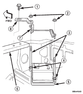
Fig. 19 Battery Hold Downs Remove/Install
2 - NUT AND WASHER (2)
3 - T-BOLT (2)
4 - RETAINER (2)
5 - BATTERY TRAY
6 - UPPER RADIATOR CROSS MEMBER
7 - BRACKET
8 - STRAPBattery
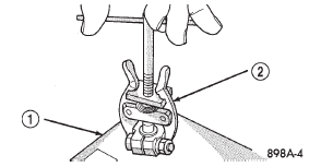
Fig. 20 Remove Battery Cable Terminal Clamp - Typical
2 - BATTERY TERMINAL PULLER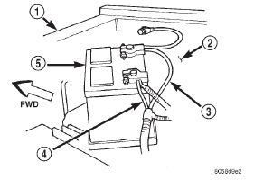
Fig. 21 Battery Cables
2 - WHEELHOUSE INNER PANEL
3 - NEGATIVE CABLE
4 - POSITIVE CABLE
5 - BATTERYBattery thermoguard
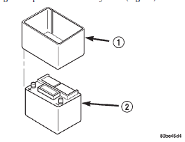
Fig. 22 Battery Thermoguard Remove/Install
2 - BATTERYBattery tray
Fig. 23 Battery Tray Remove/Install
2 - NUT AND WASHER (3)
3 - T-BOLT (2)
4 - RETAINER (2)
5 - WELD STUD (3)


Other materials:
181 FBI differential bearing preload
and gear backlash
INTRODUCTION
Differential side bearing preload and gear backlash
is achieved by selective shims positioned behind thedifferential side bearing
cones. The proper shim
thickness can be determined using slip-fit dummy
bearings D-348 in place of the differential side bearings
and a dial indicator ...