Jeep Cherokee (XJ): Service procedures
When an air conditioning system is assembled at
the factory, all components except the compressor are
refrigerant oil free. After the refrigerant system has
been charged and operated, the refrigerant oil in the
compressor is dispersed throughout the refrigerant
system. The accumulator, evaporator, condenser, and
compressor will each retain a significant amount of
the needed refrigerant oil.
It is important to have the correct amount of oil in
the refrigerant system. This ensures proper lubrication
of the compressor. Too little oil will result in
damage to the compressor. Too much oil will reduce
the cooling capacity of the air conditioning system.
It will not be necessary to check the oil level in the
compressor or to add oil, unless there has been an oil
loss. An oil loss may occur due to a rupture or leak
from a refrigerant line, a connector fitting, a component,
or a component seal. If a leak occurs, add 30
milliliters (1 fluid ounce) of refrigerant oil to the
refrigerant system after the repair has been made.
Refrigerant oil loss will be evident at the leak point
by the presence of a wet, shiny surface around the
leak.
Refrigerant oil must be added when a accumulator,
evaporator coil, or condenser are replaced. See the
Refrigerant Oil Capacities chart. When a compressor is replaced, the refrigerant
oil must be drained from
the old compressor and measured. Drain all of the
refrigerant oil from the new compressor, then fill the
new compressor with the same amount of refrigerant
oil that was drained out of the old compressor.
WARNING: REVIEW THE WARNINGS AND CAUTIONS
IN THE GENERAL INFORMATION SECTION
NEAR THE FRONT OF THIS GROUP BEFORE
RECOVERING REFRIGERANT.
A R-134a refrigerant recovery/recycling/charging
station that meets SAE Standard J2210 must be
used to recover the refrigerant from an R-134a refrigerant
system. Refer to the operating instructions supplied
by the equipment manufacturer for the proper
care and use of this equipment. WARNING: REVIEW THE WARNINGS AND CAUTIONS
IN THE GENERAL INFORMATION SECTION
NEAR THE FRONT OF THIS GROUP BEFORE EVACUATING
THE SYSTEM.
If the refrigerant system has been open to the
atmosphere, it must be evacuated before the system
can be charged. If moisture and air enters the system
and becomes mixed with the refrigerant, the compressor
head pressure will rise above acceptable
operating levels. This will reduce the performance of
the air conditioner and damage the compressor.
Evacuating the refrigerant system will remove the
air and boil the moisture out of the system at near
room temperature. To evacuate the refrigerant system,
use the following procedure:
(1) Connect a R-134a refrigerant recovery/recycling/
charging station that meets SAE Standard
J2210 and a manifold gauge set to the refrigerant
system of the vehicle.
(2) Open the low and high side valves and start
the charging station vacuum pump. When the suction
gauge reads 88 kPa (26 in. Hg.) vacuum or
greater, close all of the valves and turn off the vacuum
pump.
(a) If the refrigerant system fails to reach the
specified vacuum, the system has a leak that must
be corrected. See Refrigerant System Leaks in the
Diagnosis and Testing section of this group for the
procedures.
(b) If the refrigerant system maintains the specified
vacuum for five minutes, restart the vacuum
pump, open the suction and discharge valves and
evacuate the system for an additional ten minutes.
(3) Close all of the valves, and turn off the charging
station vacuum pump.
(4) The refrigerant system is now ready to be
charged with R-134a refrigerant. See Refrigerant
System Charge in the Service Procedures section of
this group. WARNING: REVIEW THE WARNINGS AND CAUTIONS
IN THE FRONT OF THIS GROUP BEFORE
CHARGING THE REFRIGERANT SYSTEM.
After the refrigerant system has been tested for
leaks and evacuated, a refrigerant charge can be
injected into the system. See Refrigerant Charge
Capacity for the proper amount of the refrigerant
charge.
A R-134a refrigerant recovery/recycling/charging
station that meets SAE Standard J2210 must be
used to charge the refrigerant system with R-134a
refrigerant. Refer to the operating instructions supplied
by the equipment manufacturer for proper care
and use of this equipment. REFRIGERANT CHARGE CAPACITY The R-134a refrigerant system charge capacity for
this vehicle is 0.567 kilograms (1.25 pounds). WARNING: EYE PROTECTION MUST BE WORN
WHEN SERVICING AN AIR CONDITIONING REFRIGERANT
SYSTEM. TURN OFF (ROTATE CLOCKWISE)
ALL VALVES ON THE EQUIPMENT BEING USED,
BEFORE CONNECTING TO OR DISCONNECTING
FROM THE REFRIGERANT SYSTEM. FAILURE TO
OBSERVE THESE WARNINGS MAY RESULT IN PERSONAL
INJURY.
When servicing the air conditioning system, a
R-134a refrigerant recovery/recycling/charging station
that meets SAE Standard J2210 must be used.
Contact an automotive service equipment supplier for
refrigerant recovery/recycling/charging equipment.
Refer to the operating instructions supplied by the equipment manufacturer for
proper care and use of
this equipment.
A manifold gauge set may be needed with some
recovery/recycling/charging equipment (Fig. 13). The
service hoses on the gauge set being used should
have manual (turn wheel), or automatic back-flow
valves at the service port connector ends. This will
prevent refrigerant from being released into the
atmosphere.
1 - HIGH PRESSURE GAUGE MANIFOLD GAUGE SET CONNECTIONS CAUTION: Do not use an R-12 manifold gauge set
on an R-134a system. The refrigerants are not compatible
and system damage will result.
LOW PRESSURE GAUGE HOSE The low pressure
hose (Blue with Black stripe) attaches to the suction
service port. This port is located on the suction line
between the accumulator outlet and the compressor.
HIGH PRESSURE GAUGE HOSE The high pressure
hose (Red with Black stripe) attaches to the discharge
service port. This port is located on the
discharge line between the compressor and the condenser
inlet.
RECOVERY/RECYCLING/EVACUATION/CHARGING
HOSE The center manifold hose (Yellow, or
White, with Black stripe) is used to recover, evacuate,
and charge the refrigerant system. When the low
or high pressure valves on the manifold gauge set
are opened, the refrigerant in the system will escape
through this hose.Refrigerant oil level
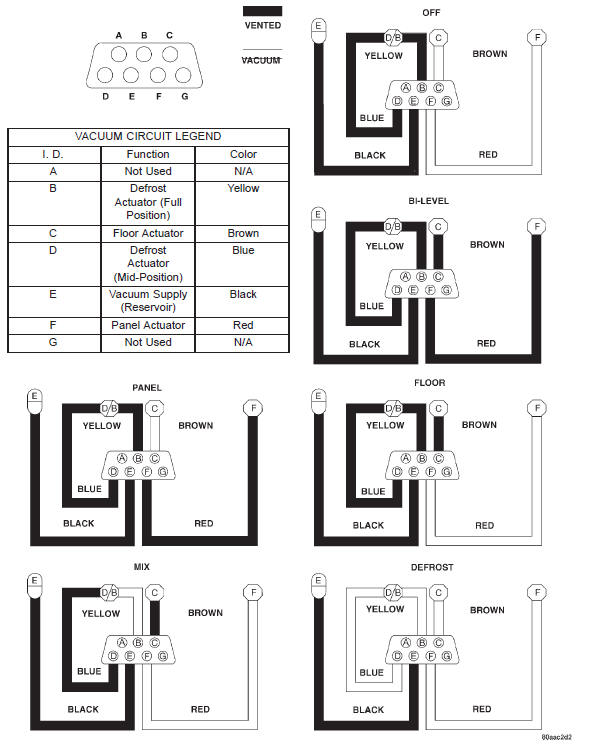
Fig. 11 Vacuum Circuits - Heater Only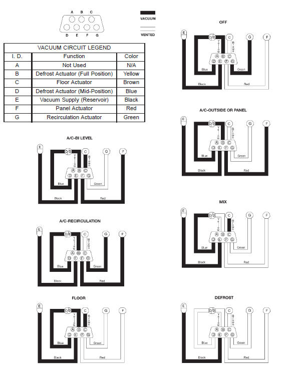
Fig. 12 Vacuum Circuits - Heater-A/C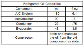
Refrigerant recovery
Refrigerant system evacuate
Refrigerant system charge
Refrigerant system service
equipment
Fig. 13 Manifold Gauge Set - Typical
2 - VALVE
3 - VACUUM/REFRIGERANT HOSE (YELLOW W/BLACK
STRIPE)
4 - HIGH PRESSURE HOSE (RED W/BLACK STRIPE)
5 - LOW PRESSURE HOSE (BLUE W/BLACK STRIPE)
6 - VALVE
7 - LOW PRESSURE GAUGE
 Low pressure cycling clutch switch. Refrigerant system leaks. Vacuum system

Other materials:
Engine break-in recommendations
A long break-in period is not required for the engine and
drivetrain (transmission and axle) in your vehicle.
Drive moderately during the first 300 miles (500 km).
After the initial 60 miles (100 km), speeds up to 50 or
55 mph (80 or 90 km/h) are desirable.
While cruising, brief full-thro ...