Jeep Cherokee (XJ): Speedometer adapter. Speed sensor rotor-speedometer drive gear. Park/neutral position switch
Rear axle gear ratio and tire size determine speedometer
pinion requirements. REMOVAL (1) Raise vehicle.
(2) Disconnect wires from vehicle speed sensor.
(3) Remove adapter clamp and screw (Fig. 51).
(4) Remove speed sensor and speedometer adapter
as assembly.
(5) Remove speed sensor retaining screw and
remove sensor from adapter.
(6) Remove speedometer pinion from adapter.
1 - RETAINER BOLT (7) Inspect sensor and adapter O-rings (Fig. 51).
Remove and discard O-rings if worn or damaged.
(8) Inspect terminal pins in speed sensor. Clean
pins with Mopart electrical spray cleaner if dirty or
oxidized. Replace sensor if faulty, or pins are loose,
severely corroded, or damaged. INSTALLATION (1) Thoroughly clean adapter flange and adapter
mounting surface in housing. Surfaces must be clean
for proper adapter alignment and speedometer operation.
(2) Install new O-rings on speed sensor and speedometer
adapter if necessary (Fig. 51).
(3) Lubricate sensor and adapter O-rings with
transmission fluid.
(4) Install vehicle speed sensor in speedometer
adapter. Tighten sensor attaching screw to 2-3 N·m
(15-27 in. lbs.) torque.
(5) Install speedometer pinion in adapter.
(6) Count number of teeth on speedometer pinion.
Do this before installing assembly in housing. Then
lubricate pinion teeth with transmission fluid.
(7) Note index numbers on adapter body (Fig. 52).
These numbers will correspond to number of teeth on
pinion.
(8) Install speedometer assembly in housing.
(9) Rotate adapter until required range numbers
are at 6 o'clock position. Be sure range index numbers
correspond to number of teeth on pinion gear. (10) Install speedometer adapter clamp and retaining
screw. Tighten clamp screw to 10-12 N·m (90-110
in. lbs.) torque.
(11) Connect wires to vehicle speed sensor.
(12) Lower vehicle and top off transmission fluid
level, if necessary. REMOVAL (1) Raise vehicle.
(2) Remove components necessary to gain access to
rotor and drive gear such as propeller shaft, transfer
case, crossmember, and shift linkage.
(3) Disengage wire connector from the output
speed sensor.
(4) Remove the bolt holding the output speed sensor
to the adapter housing.
(5) Remove the output speed sensor from the
adapter housing.
(6) Remove the bolts holding the adapter housing
to the transmission case.
(7) Tap the adapter housing at the joint line gently
with a rubber mallet to separate the adapter housing
from the transmission case.
(8) Remove the adapter housing from the transmission
case.
1 - SENSOR O-RING
1 - SPEEDOMETER ADAPTER (9) Remove speedometer drive gear snap ring (Fig.
53).
(10) Remove the speedometer drive gear and
spacer, if equipped.
(11) Remove rotor from the output shaft. It may be
necessary to use a wood dowel or hammer handle
(Fig. 54) to gently pry the rotor from the output shaft. Be sure to retrieve the
rotor locating key from
the output shaft or rotor.
1 - ROTOR
1 - WOOD DOWEL OR HAMMER HANDLE INSTALLATION (1) Clean sealing surfaces of transmission case and
extension/adaptor housing.
(2) Install rotor, spacer (if equipped) and drive
gear on output shaft. Then install drive gear snap
ring (Fig. 53).
(3) Apply 1/8 3/16 inch wide bead of Threebondt
Liquid Gasket TB1281, P/N 83504038, to transmission
case sealing surface and install extension/
adapter housing on case.
(4) Tighten adaptor housing bolts to 34 N·m (25 ft.
lbs.) torque.
(5) Install components removed to gain access to
rotor and drive gear. REMOVAL (1) Raise vehicle.
(2) Disconnect switch wire harness connector.
(3) Pry washer lock tabs upward and remove
switch attaching nut and tabbed washer (Fig. 55).
(4) Remove switch adjusting bolt (Fig. 55).
(5) Slide switch off manual valve shaft
1 - ADJUSTING BOLT INSTALLATION (1) Disconnect shift linkage rod from shift lever on
left side of transmission.
(2) Rotate manual shift lever all the way rearward.
Then rotate lever forward two detent positions
to Neutral.
(3) Install switch on manual valve shaft and
install switch adjusting bolt finger tight. Do not
tighten bolt at this time.
(4) Install tabbed washer on manual valve shaft
and install switch attaching nut. Tighten nut to 6.9
N·m (61 in. lbs.) torque but do not bend washer lock
tabs over nut at this time.
(5) Verify that transmission is in Neutral.
(6) Rotate switch to align neutral standard line
with vertical groove on manual valve shaft (Fig. 56).
(7) Align switch standard line with groove or flat
on manual valve shaft.
1 - NEUTRAL STANDARD LINE (8) Tighten switch adjusting bolt to 13 N·m (9 ft.
lbs.) torque.
(9) Bend at least two washer lock tabs over switch
attaching nut to secure it.
(10) Connect shift linkage rod to shift lever on left
side of case.
(11) Connect switch wires to harness and lower
vehicle.
(12) Check switch operation. Engine should start
in Park and Neutral only.Speedometer adapter
Fig. 50 Transmission Speed Sensor Removal/Installation
2 - SPEED SENSORSpeed sensor rotor-speedometer
drive gear
Fig. 52 Index Numbers On Speedometer Pinion Adapter
2 - SPEEDOMETER ADAPTER
3 - ADAPTER O-RING
4 - SPEEDOMETER PINION
5 - ADAPTER CLAMP
6 - VEHICLE SPEED SENSOR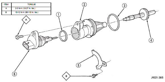
Fig. 51 Speedometer Pinion Adapter Components
2 - INDEX NUMBER LOCATION
Fig. 53 Removing/Installation Speedometer Drive Gear
2 - SPEEDOMETER DRIVE GEAR
3 - SNAP RING
Fig. 54 Removing Speed Sensor Rotor
2 - ROTOR
3 - OUTPUT SHAFTPark/neutral position switch
Fig. 55 Park/Neutral Position Switch Removal/Installation
2 - ATTACHING NUT
3 - NEUTRAL SWITCH
4 - TABBED WASHER
Fig. 56 Park/Neutral Position Switch Adjustment
2 - ADJUSTING BOLT
3 - VERTICAL GROOVE ON MANUAL VALVE SHAFT
 Torque converter. Adapter housing seal. Speed sensor
 Gearshift cable. Brake transmission shift interlock. Transmission valve body solenoids
Other materials:
Engine compartment
ENGINE COMPARTMENT - 2.4L
1 - Air Cleaner Filter
2 - Engine Coolant Pressure Cap
3 - Oil Fill Cap
4 - Brake Fluid Reservoir
5 - Power Distribution Center (Fuses)
6 - Battery
7 - Washer Fluid Reservoir
8 - Engine Oil Dipstick
ENGINE COMPARTMENT - 3.2L
1 - Engine Coolant Reservoir
2 ...