Jeep Cherokee (XJ): Starter motor noise - 2.5L engine. Starter motor. Starter relay
See the Starter Motor Noise Diagnosis chart (Fig.
9). If the complaint is similar to Conditions 1 and 2
in the chart, correction can be made by placing shims
between the starter motor and the engine block using
the following procedures: CONDITION POSSIBLE CAUS CORRECTION NOTE: A high frequency whine during cranking is normal for this
starter motor. FIG. 9 STARTER MOTOR NOISE DIAGNOSIS (1) If the complaint is similar to Condition 1, the
starter motor must be moved toward the starter ring
gear by removing shims from both starter mounting
pads on the engine block (Fig. 10). Refer to Starter
Motor in the index of this service manual for the
location of the proper starter motor removal and
installation procedures.
NOTE: The shim thickness is 0.381 mm (0.015 in.).
These shims may be stacked if additional thickness
is required.
1 - STARTER MOTOR SHIM (2) If the complaint is similar to Condition 2, the
starter motor must be moved away from the starter
ring gear. This is done by installing shim(s) across
both starter mounting pads on the engine block.
More than one shim may be required. Refer to
Starter Motor in the index of this service manual
for the location of the proper removal and installation
procedures.
NOTE: This is a condition that will generally cause
broken starter (flywheel/torque converter drive
plate) ring gear teeth or broken starter motor housings. Correct starter motor operation can be confirmed
by performing the following free running bench test.
This test can only be performed with the starter
motor removed from the vehicle. Refer to Starting
System in the index of this service manual for the
location of the proper starter motor specifications.
CAUTION: The 2.5L engine uses a permanent magnet
starter. Permanent magnet starters are highly
sensitive to hammering, shocks, external pressure
and reverse polarity. This starter motor must never
be clamped in a vise by the starter field frame. The
starter should only be clamped by the mounting
flange. Do not reverse the battery cable connections
to this starter motor when testing. The permanent
magnets may be damaged and the starter
rendered unserviceable if it is subjected to any of
these conditions. STARTER MOTOR (1) Remove the starter motor from the vehicle.
Refer to Starter Motor in the index of this service
manual for the location of the proper starter motor
removal and installation procedures.
(2) Mount the starter motor securely in a softjawed
bench vise. The vise jaws should be clamped
on the mounting flange of the starter motor. Never
clamp on the starter motor by the field frame.
(3) Connect a suitable volt-ampere tester and a
12-volt battery to the starter motor in series, and set
the ammeter to the 100 ampere scale. See the
instructions provided by the manufacturer of the
volt-ampere tester being used.
(4) Install a jumper wire from the solenoid terminal
to the solenoid B(+) terminal stud. The starter
motor should operate. If the starter motor fails to
operate, replace the faulty starter motor.
(5) Adjust the carbon pile load of the tester to
obtain the free running test voltage. Refer to Starting
System in the index of this service manual for
the location of the proper starter motor free running
test voltage specifications.
(6) Note the reading on the ammeter and compare
this reading to the free running test maximum
amperage draw. Refer to Starting System in the
index of this service manual for the location of the
proper starter motor free running test maximum
amperage draw specifications.
(7) If the ammeter reading exceeds the maximum
amperage draw specification, replace the faulty
starter motor. STARTER SOLENOID This test can only be performed with the starter
motor removed from the vehicle.
(1) Remove the starter motor from the vehicle.
Refer to Starter Motor in the index of this service
manual for the location of the proper starter motor
removal and installation procedures.
(2) Disconnect the wire from the solenoid field coil
terminal.
(3) Check for continuity between the solenoid terminal
and the solenoid field coil terminal with a continuity
tester (Fig. 11). There should be continuity. If
OK, go to Step 4. If not OK, replace the faulty starter
motor.
(4) Check for continuity between the solenoid terminal
and the solenoid case (Fig. 12). There should
be continuity. If not OK, replace the faulty starter
motor. The starter relay (Fig. 13) is located in the Power
Distribution Center (PDC), in the engine compartment.
Refer to the fuse and relay layout label affixed to the underside of the PDC
cover for starter relay
identification and location. Refer to Starting System
in the index of this service manual for the location
of complete starting system wiring diagrams.
1 - SOLENOID
2 - SOLENOID TERMINAL
3 - OHMMETER
4 - FIELD COIL TERMINAL
1 - SOLENOID
2 - SOLENOID TERMINAL
3 - OHMMETER RELAY TEST (1) Remove the starter relay from the PDC. Refer
to Starter Relay in the index of this service manual
for the location of the proper starter relay removal
and installation procedures.
(2) A relay in the de-energized position should
have continuity between terminals 87A and 30, and
no continuity between terminals 87 and 30. If OK, go
to Step 3. If not OK, replace the faulty relay.
(3) Resistance between terminals 85 and 86 (electromagnet)
should be 75 6 5 ohms. If OK, go to Step
4. If not OK, replace the faulty relay.
(4) Connect a battery to terminals 85 and 86.
There should now be continuity between terminals
30 and 87, and no continuity between terminals 87A
and 30. If OK, perform the Relay Circuit Test that
follows. If not OK, replace the faulty relay
RELAY CIRCUIT TEST (1) The relay common feed terminal cavity (30) is
connected to battery voltage and should be hot at all
times. If OK, go to Step 2. If not OK, repair the open
circuit to the fused B(+) fuse in the PDC as required.
(2) The relay normally closed terminal (87A) is
connected to terminal 30 in the de-energized position,
but is not used for this application. Go to Step 3.
(3) The relay normally open terminal (87) is connected
to the common feed terminal (30) in the energized
position. This terminal supplies battery voltage
to the starter solenoid field coil. There should be continuity
between the cavity for relay terminal 87 and
the starter solenoid terminal at all times. If OK, go
to Step 4. If not OK, repair the open engine starter
motor relay output circuit to the starter solenoid as
required.
(4) The coil battery terminal (86) is connected to
the electromagnet in the relay. It is energized when
the ignition switch is held in the Start position. On
vehicles with a manual transmission, the clutch
pedal must be blocked in the fully depressed position
for this test. Check for battery voltage at the cavity
for relay terminal 86 with the ignition switch in the
Start position, and no voltage when the ignition
switch is released to the On position. If OK, go to
Step 5. If not OK with a manual transmission, disconnect
the clutch pedal position switch wire harness
connector and install a jumper wire between the two
cavities in the body half of the connector and check
for battery voltage again at the cavity for relay terminal
86. If now OK, replace the faulty clutch pedal
position switch. If still not OK with a manual transmission
or if not OK with an automatic transmission,
check for an open or shorted fused ignition switch
output (start) circuit to the ignition switch and
repair, as required. If the fused ignition switch output
(start) circuit is OK, refer to Ignition Switch
and Key Lock Cylinder in the index of this service
manual for the location of the proper ignition switch
diagnosis and testing procedures.
(5) The coil ground terminal (85) is connected to
the electromagnet in the relay. On vehicles with a
manual transmission, it is grounded at all times. On
vehicles with an automatic transmission, it is
grounded through the park/neutral position switch
only when the gearshift selector lever is in the Park
or Neutral positions. Check for continuity to ground
at the cavity for relay terminal 85. If not OK with a
manual transmission, repair the open park/neutral
position switch sense circuit to ground as required. If
not OK with an automatic transmission, check for an
open or shorted park/neutral position switch sense
circuit to the park/neutral position switch and repair,
as required. If the park/neutral position switch sense
circuit checks OK, refer to Park/Neutral Position
Switch in the index of this service manual for the
location of the proper park/neutrStarter motor noise - 2.5L engine
1. VERY HIGH FREQUENCY
WHINE BEFORE ENGINE
STARTS; ENGINE STARTS OK.
1. Excessive distance between pinion
gear and flywheel/drive plate gear.
1. Move starter motor toward
flywheel/drive plate by removing
shim(s), if possible.
2. VERY HIGH FREQUENCY
WHINE AFTER ENGINE STARTS
WITH IGNITION KEY RELEASED.
ENGINE STARTS OK.
2. Insufficient distance between
starter motor pinion gear and
flywheel/drive plate runout can cause
noise to be intermittent.
2. Shim starter motor away from
flywheel/drive plate. Inspect
flywheel/drive plate for damage;
bent, unusual wear, and excessive
runout. Replace flywheel/drive
plate as necessary.
3. A LOUD "WHOOP" AFTER
ENGINE STARTS WHILE
STARTER MOTOR IS ENGAGED.
3. Most probably cause is defective
overrunning clutch.
3. Replace starter motor.
4. A "RUMBLE," "GROWL," OR
"KNOCK" AS STARTER MOTOR
COASTS TO STOP AFTER
ENGINE STARTS.
4. Most probable cause is bent or
unbalanced starter motor armature.
4. Replace starter motor.
Fig. 10 Starter Motor ShimStarter motor
Starter relay
Fig. 11 Continuity Test Between Solenoid Terminal and Field Coil Terminal
- Typical
Fig. 12 Continuity Test Between Solenoid Terminal and Solenoid Case -
Typical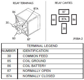
Fig. 13 Starter Relay


Other materials:
Power Seats. Manual Seats. Front Heated Seats
Power Seats - If Equipped
Some models may be equipped with a power driver's
seat. The power seat switch is located on the outboard
side of the seat near the floor. Use the switch to move the
seat up, down, forward or rearward.
Power Seat SwitchReclining The Seatback Forward Or Rearward
The s ...