Jeep Cherokee (XJ): Tires
DESCRIPTION Tires are designed and engineered for each specific
vehicle. They provide the best overall performance
for normal operation. The ride and handling characteristics
match the vehicle's requirements. With
proper care they will give excellent reliability, traction,
skid resistance, and tread life.
Driving habits have more effect on tire life than
any other factor. Careful drivers will obtain in most
cases, much greater mileage than severe use or careless
drivers. A few of the driving habits which will
shorten the life of any tire are: Radial-ply tires are more prone to irregular tread
wear. It is important to follow the tire rotation interval
shown in the section on Tire Rotation. This will
help to achieve a greater tread life. TIRE IDENTIFICATION Tire type, size, aspect ratio and speed rating are
encoded in the letters and numbers imprinted on the
side wall of the tire. Refer to the chart to decipher
the tire identification code (Fig. 1).
Performance tires have a speed rating letter after
the aspect ratio number.
The speed rating is not always printed on the tire
sidewall.
TIRE CHAINS Tire snow chains may be used on certain models.
Refer to the Owner's Manual for more information. DESCRIPTION Radial-ply tires improve handling, tread life and
ride quality, and decrease rolling resistance.
Radial-ply tires must always be used in sets of
four. Under no circumstances should they be used on
the front only. They may be mixed with temporary
spare tires when necessary. A maximum speed of 50
MPH is recommended while a temporary spare is in
use.
Radial-ply tires have the same load-carrying capacity
as other types of tires of the same size. They also
use the same recommended inflation pressures.
The use of oversized tires, either in the front or
rear of the vehicle, can cause vehicle drive train failure.
This could also cause inaccurate wheel speed
signals when the vehicle is equipped with Anti-Lock
Brakes.
The use of tires from different manufactures on the
same vehicle is NOT recommended. The proper tire
pressure should be maintained on all four tires. DESCRIPTION The temporary spare tire is designed for emergency
use only. The original tire should be repaired
or replaced at the first opportunity, then reinstalled.
Do not exceed speeds of 50 M. P. H. when using the
temporary spare tire. Refer to Owner's Manual for
complete details. Under inflation will cause rapid shoulder wear, tire
flexing, and possible tire failure (Fig. 2).
1 - THIN TIRE THREAD AREAS Over inflation will cause rapid center wear and
loss of the tire's ability to cushion shocks (Fig. 3).
1 - THIN TIRE THREAD AREA Improper inflation can cause: For proper tire pressure specification refer to the
Tire Inflation Pressure Chart provided with the vehicle.
Tire pressures have been chosen to provide safe
operation, vehicle stability, and a smooth ride. Tire
pressure should be checked cold once a month. The
spare tire pressure should be check at least twice
annually. Tire pressure decreases as the ambient
temperature drops. Check tire pressure frequently
when ambient temperature varies widely.
Inflation pressures specified on the placards are
cold inflation pressure. The vehicle must sit for at
least 3 hours to obtain the correct cold inflation pressure
reading. Or driven less than one mile after sitting
for 3 hours. Tire inflation pressures may
increase from 2 to 6 pounds per square inch (psi)
during operation, due to increased tire temperature.
WARNING: OVER OR UNDER INFLATED TIRES
CAN AFFECT VEHICLE HANDLING AND TREAD
WEAR. THIS MAY CAUSE THE TIRE TO FAIL SUDDENLY,
RESULTING IN LOSS OF VEHICLE CONTROL. DESCRIPTION Where speed limits allow the vehicle to be driven
at high speeds, correct tire inflation pressure is very
important. For speeds up to and including 120 km/h
(75 mph), tires must be inflated to the pressures
shown on the tire placard. For continuous speeds in
excess of 120 km/h (75 mph), tires must be inflated
to the maximum pressure specified on the tire sidewall.
Vehicles loaded to the maximum capacity should
not be driven at continuous speeds above 75 mph
(120 km/h).
For emergency vehicles that are driven at speeds
over 90 mph (144 km/h), special high speed tires
must be used. Consult tire manufacturer for correct
inflation pressure recommendations. DESCRIPTION The original equipment tires provide a proper balance
of many characteristics such as: It is recommended that tires equivalent to the original
equipment tires be used when replacement is
needed.
Failure to use equivalent replacement tires may
adversely affect the safety and handling of the vehicle.
The use of oversize tires may cause interference
with vehicle components. Under extremes of suspension
and steering travel, interference with vehicle
components may cause tire damage.
WARNING: FAILURE TO EQUIP THE VEHICLE WITH
TIRES HAVING ADEQUATE SPEED CAPABILITY
CAN RESULT IN SUDDEN TIRE FAILURE. Pressure gauges A quality air pressure gauge is recommended to
check tire pressure. After checking the air pressure,
replace valve cap finger tight. Tread wear indicators Tread wear indicators are molded into the bottom
of the tread grooves. When tread depth is 1.6 mm
(1/16 in.), the tread wear indicators will appear as a
13 mm (1/2 in.) band (Fig. 4).
Tire replacement is necessary when indicators
appear in two or more grooves or if localized balding
occurs. Tire wear patterns Under inflation will cause wear on the shoulders of
tire. Over inflation will cause wear at the center of
tire.
Excessive camber causes the tire to run at an
angle to the road. One side of tread is then worn
more than the other (Fig. 5).
Excessive toe-in or toe-out causes wear on the
tread edges and a feathered effect across the tread
(Fig. 5). Tire noise or vibration Radial-ply tires are sensitive to force impulses
caused by improper mounting, vibration, wheel
defects, or possibly tire imbalance.
To find out if tires are causing the noise or vibration,
drive the vehicle over a smooth road at varying speeds. Note the noise level
during acceleration,
deceleration and slight left and right steering inputs.
1 - THREAD ACCEPTABLE ROTATION Tires on the front and rear operate at different
loads and perform different steering, driving, and
braking functions. For these reasons they wear at
unequal rates and tend to develop irregular wear
patterns. These effects can be reduced by rotating
the tires at regular intervals. The benefits of tire
rotation are: The suggested method of tire rotation is (Fig. 6).
Other rotation methods can be used, but they will
not provide all the tire longevity benefits.
Tires and wheels are currently match mounted at
the factory. Match mounting is a technique used to
reduce runout in the wheel/tire assembly. This means
that the high spot of the tire is aligned with the low
spot on the wheel rim. The high spot on the tire is
marked with a paint mark or a bright colored adhesive
label on the outboard sidewall. The low spot on
the rim is identified with a label on the outside of the
rim and a dot on the inside of the rim. If the outside
label has been removed the tire will have to be
removed to locate the dot on the inside of the rim.
Before dismounting a tire from its wheel, a reference
mark should be placed on the tire at the valve
stem location. This reference will ensure that it is
remounted in the original position on the wheel.
(1) Use a dial indicator to locate the high spot of
the tire on the center tread rib (Fig. 7). Record the
indicator reading and mark the high spot on the tire.
Place a mark on the tire at the valve stem location
(Fig. 8).
1 - REFERENCE MARK (2) Break down the tire and remount it 180
degrees on the rim (Fig. 9).
Fig. 9 Remount Tire 180 Degrees 1 - VALVE STEM (3) Measure the total runout again and mark the
tire to indicate the high spot.
(4) If runout is still excessive use the following
procedures.
(a) If the high spot is within 101.6 mm (4.0 in.)
of the first spot and is still excessive, replace the
tire.
(b) If the high spot is within 101.6 mm (4.0 in.)
of the first spot on the wheel, the wheel may be out
of specifications. Refer to Wheel and Tire Runout.
(c) If the high spot is NOT within 101.6 mm (4.0
in.) of either high spot, draw an arrow on the tread
from second high spot to first. Break down the tire
and remount it 90 degrees on rim in that direction
(Fig. 10). This procedure will normally reduce the
runout to an acceptable amount. For proper repairing, a radial tire must be removed
from the wheel. Repairs should only be made if the
defect, or puncture, is in the tread area (Fig. 11). The
tire should be replaced if the puncture is located in
the sidewall.
1 - 2ND HIGH SPOT ON TIRE Deflate tire completely before removing the tire
from the wheel. Use lubrication such as a mild soap
solution when dismounting or mounting tire. Use
tools free of burrs or sharp edges which could damage
the tire or wheel rim.
Before mounting tire on wheel, make sure all rust
is removed from the rim bead and repaint if necessary.
Install wheel on vehicle, and tighten to proper
torque specification. CLEANING TIRES Remove the protective coating on the tires before
delivery of a vehicle. This coating may cause deterioration
of the tires.
1 - REPAIRABLE AREA To remove the protective coating, apply warm
water and let it soak for a few minutes. Afterwards,
scrub the coating away with a soft bristle brush.
Steam cleaning may also be used to remove the coating.
NOTE: DO NOT use gasoline, mineral oil, oil-based
solvent or a wire brush for cleaning. TIRE SIZEDescription and operation
Tires
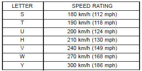
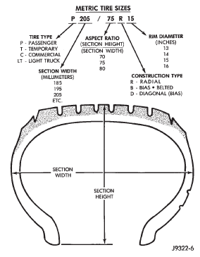
Fig. 1 Tire IdentificationRadial-ply tires
Spare tire-temporary
Tire inflation pressures
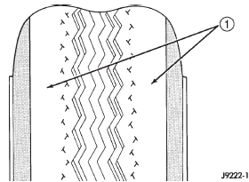
Fig. 2 Under Inflation Wear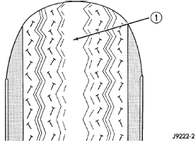
Fig. 3 Over Inflation Wear
Tire pressure for high speed
Replacement tires
Diagnosis and testing
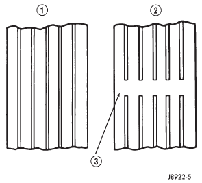
Fig. 4 Tread Wear Indicators
2 - THREAD UNACCEPTABLE
3 - WEAR INDICATORService procedures
Rotation
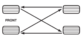
Fig. 6 Tire Rotation PatternMatch mounting
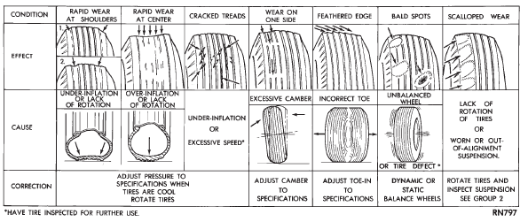
Fig. 5 Tire Wear Patterns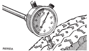
Fig. 7 Dial Indicator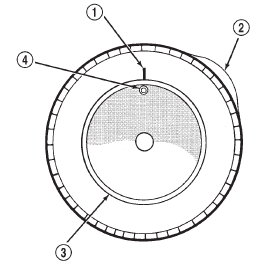
Fig. 8 First Measurement On Tire
2 - 1ST MEASUREMENT
HIGH SPOT MARK TIRE AND RIM
3 - WHEEL
4 - VALVE STEM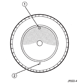
2 - REFERENCE MARKRepairing leaks
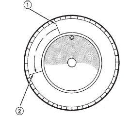
Fig. 10 Remount Tire 90 Degrees In Direction of Arrow
2 - 1ST HIGH SPOT ON TIRECleaning and inspection
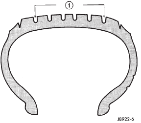
Fig. 11 Tire Repair AreaSpecifications


Other materials:
Headlamp alignment
Service procedures
Headlamp alignment
Headlamps can be aligned using the screen method
provided in this section. Alignment Tool C-4466-A or
equivalent can also be used. Refer to instructions
provided with the tool for proper procedures.Lamp alignment screen preparation
(1) Position vehicle on a l ...