Jeep Cherokee (XJ): Torque converter. Adapter housing seal. Speed sensor
REMOVAL (1) Remove transmission and torque converter
from vehicle.
(2) Place a suitable drain pan under the converter
housing end of the transmission.
CAUTION: Verify that transmission is secure on the
lifting device or work surface, the center of gravity
of the transmission will shift when the torque converter
is removed creating an unstable condition.
The torque converter is a heavy unit. Use caution
when separating the torque converter from the
transmission.
(3) Pull the torque converter forward until the center
hub clears the oil pump seal.
(4) Separate the torque converter from the transmission. INSTALLATION Check converter hub and drive notches for sharp
edges, burrs, scratches, or nicks. Polish the hub and
notches with 320/400 grit paper or crocus cloth if necessary.
The hub must be smooth to avoid damaging
the pump seal at installation.
(1) Lubricate converter hub and oil pump seal lip
with transmission fluid.
(2) Place torque converter in position on transmission.
CAUTION: Do not damage oil pump seal or bushing
while inserting torque converter into the front of the
transmission.
(3) Align torque converter to oil pump seal opening.
(4) Insert torque converter hub into oil pump.
(5) While pushing torque converter inward, rotate
converter until converter is fully seated in the oil
pump gears.
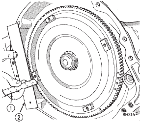
(6) Check converter seating with a scale and
straightedge (Fig. 48). Surface of converter lugs
should be 1/2 in. to rear of straightedge when converter
is fully seated.
(7) If necessary, temporarily secure converter with
C-clamp attached to the converter housing.
(8) Install the transmission in the vehicle.
(9) Fill the transmission with the recommended
fluid.
1 - SCALE REMOVAL (1) Raise vehicle.
(2) Disconnect or remove components necessary to
gain access to seal (e.g. propeller shaft, crossmember,
shift linkage, transfer case, exhaust components,
hoses, wires).
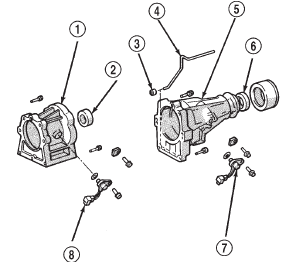
(3) On 4X2 vehicles, remove dust shield from the
adapter housing by tapping gently with a brass drift
and hammer (Fig. 49).
(4) On 4X2 vehicles, remove the adapter housing
seal with Seal Puller 7550.
(5) On 4X4 vehicles, remove the adapter housing
seal using a slide hammer mounted screw. INSTALLATION (1) Install new adapter housing seal with Seal
Installer 7888.
(2) On 4X2 vehicles, install dust shield using Special
Tool D-187-B.
(3) Reinstall components removed to gain access to
seal.
(4) Top off transmission fluid if necessary. REMOVAL (1) Disconnect sensor wire harness connector.
1 - 4WD ADAPTER HOUSING (2) Remove sensor retainer bolt and remove sensor
(Fig. 50).
(3) Remove and discard speed sensor O-ring. INSTALLATION (1) Install new O-ring on speed sensor and install
sensor in transmission case.
(2) Install sensor bracket and retainer bolt.
Tighten bolt to 7.4 N·m (65 in. lbs.) torque.
(3) Connect sensor wire harness connector.Torque converter

Fig. 48 Checking Torque Converter Seating
2 - STRAIGHTEDGEAdapter housing seal
Speed sensor

Fig. 49 Adapter Housing Seals
2 - SEAL
3 - BUSHING
4 - OIL TUBE
5 - 2WD EXTENSION HOUSING
6 - SEAL
7 - SPEED SENSOR
8 - SPEED SENSOR
 Transmission and torque converter
 Speedometer adapter. Speed sensor rotor-speedometer
drive gear. Park/neutral position switch
Other materials:
Removal and installation
Overhead console
(1) Disconnect and isolate the battery negative
cable.
(2) Remove the two screws located forward of the
display module that secure the overhead console to
the upper windshield opening reinforcement (Fig. 3).
(3) To release the overhead console from the rear
mounting bracke ...
