Jeep Cherokee (XJ): 30RH automatic transmission
DESCRIPTION
The 30RH automatic transmission is used with the 2.5L engine (Fig. 1). The 30RH is three speed transmissions with a lock-up clutch in the torque converter.
The transmissions contain a front and rear clutch which function as the input driving components.
They also contain the kickdown (front) and the low/reverse (rear) bands which, along with the overrunning clutch, serve as the holding components. The driving and holding components combine to select the necessary planetary gear components, in the front and rear planetary gear set, transfer the engine power from the input shaft through to the output shaft. The transmissions contain a governor that is mounted on the output shaft and supplies pressure to the valve body based on the output shaft speed.
The valve body is mounted to the lower side of the transmission and contains the valves to control pressure regulation, fluid flow control, and clutch/band application. The oil pump is mounted at the front of the transmission and is driven by the torque converter hub. The pump supplies the oil pressure necessary for clutch/band actuation and transmission lubrication. The 30RH transmission is cooled by an integral fluid cooler inside the radiator.
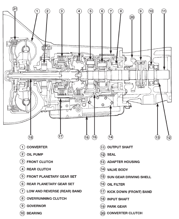
Fig. 1 30RH Automatic Transmission
TRANSMISSION IDENTIFICATION
Transmission identification numbers are stamped on the left side of the case just above the oil pan gasket surface (Fig. 2). Refer to this information when ordering replacement parts.
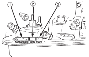
Fig. 2 Transmission Part Number And Serial Number Location
1 - PART NUMBER
2 - BUILD DATE
3 - SERIAL NUMBER
TRANSMISSION GEAR RATIOS
Forward gear ratios are:
- 2.74:1 (first gear)
- 1.54:1 (second gear)
- 1.00:1 (third gear)
OPERATION
The application of each driving or holding component is controlled by the valve body based upon the manual lever position and governor pressure. The governor pressure is a variable pressure input to the valve body and is one of the signals that a shift is necessary. First through third gear are obtained by selectively applying and releasing the different clutches and bands. Engine power is thereby routed to the various planetary gear assemblies which combine with the overrunning clutch assembly to generate the different gear ratios. The torque converter clutch is hydraulically applied and is released when fluid is vented from the hydraulic circuit by the torque converter control (TCC) solenoid on the valve body. The torque converter clutch is controlled by the Powertrain Control Module (PCM). The torque converter clutch engages in third gear when the vehicle is cruising on a level plane after the vehicle has warmed up. The torque converter clutch will disengage momentarily when an increase in engine load is sensed by the PCM, such as when the vehicle begins to go uphill or the throttle pressure is increased. The torque converter clutch feature increases fuel economy and reduces the transmission fluid temperature
PARK POWERFLOW
As the engine is running and the crankshaft is rotating, the flexplate and torque converter, which are also bolted to it, are all rotating in a clockwise direction as viewed from the front of the engine. The notched hub of the torque converter is connected to the oil pump's internal gear, supplying the transmission with oil pressure. As the converter turns, it turns the input shaft in a clockwise direction. As the input shaft is rotating, the front clutch hub-rear clutch retainer and all their associated parts are also rotating, all being directly connected to the input shaft. The power flow from the engine through the front-clutch-hub and rear-clutch-retainer stops at the rear-clutch-retainer. Therefore, no power flow to the output shaft, occurs because no clutches are applied. The only mechanism in use at this time is the parking sprag (Fig. 3), which locks the parking gear on the output shaft to the transmission case.
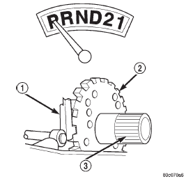
Fig. 3 Park Powerflow
1 - LEVER ENGAGED FOR PARK
2 - PARK SPRAG
3 - OUTPUT SHAFT
NEUTRAL POWERFLOW
With the gear selector in the neutral position (Fig.
4), the power flow of the transmission is essentially the same as in the park position. The only operational difference is that the parking sprag has been disengaged, unlocking the output shaft from the transmission case and allowing it to move freely.
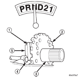
Fig. 4 Neutral Powerflow
1 - LEVER DISENGAGED FOR NEUTRAL
2 - PARK SPRAG
3 - OUTPUT SHAFT
4 - CAM
5 - LEVER
REVERSE POWERFLOW
When the gear selector is moved into the reverse position (Fig. 5), the front clutch and the rear band are applied. With the application of the front clutch, engine torque is applied to the sun gear, turning it in a clockwise direction. The clockwise rotation of the sun gear causes the rear planet pinions to rotate against engine rotation in a counterclockwise direction.
The rear band is holding the low reverse drum, which is splined to the rear carrier. Since the rear carrier is being held, the torque from the planet pinions is transferred to the rear annulus gear, which is splined to the output shaft. The output shaft in turn rotates with the annulus gear in a counterclockwise direction giving a reverse gear output. The entire transmission of torque is applied to the rear planetary gearset only. Although there is torque input to the front gearset through the sun gear, no other member of the gearset is being held. During the entire reverse stage of operation, the front planetary gears are in an idling condition.
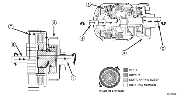
Fig. 5 Reverse Powerflow
1 - FRONT CLUTCH ENGAGED
2 - OUTPUT SHAFT
3 - LOW/REVERSE BAND APPLIED
4 - INPUT SHAFT
5 - OUTPUT SHAFT
6 - INPUT SHAFT
7 - FRONT CLUTCH ENGAGED
8 - LOW/REVERSE BAND APPLIED
FIRST GEAR POWERFLOW
When the gearshift lever is moved into the drive position the transmission goes into first gear (Fig. 6).
As soon as the transmission is shifted from park or neutral to drive, the rear clutch applies, applying the rear clutch pack to the front annulus gear. Engine torque is now applied to the front annulus gear turning it in a clockwise direction. With the front annulus gear turning in a clockwise direction, it causes the front planets to turn in a clockwise direction. The rotation of the front planets cause the sun to revolve in a counterclockwise direction. The sun gear now transfers its counterclockwise rotation to the rear planets which rotate back in a clockwise direction.
With the rear annulus gear stationary, the rear planet rotation on the annulus gear causes the rear planet carrier to revolve in a counterclockwise direction.
The rear planet carrier is splined into the low- reverse drum, and the low reverse drum is splined to the inner race of the over-running clutch. With the over-running clutch locked, the planet carrier is held, and the resulting torque provided by the planet pinions is transferred to the rear annulus gear. The rear annulus gear is splined to the output shaft and rotated along with it (clockwise) in an underdrive gear reduction mode.
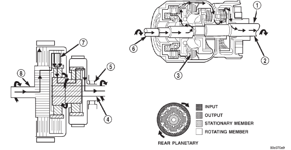
Fig. 6 First Gear Powerflow
1 - OUTPUT SHAFT
2 - OVER-RUNNING CLUTCH HOLDING
3 - REAR CLUTCH APPLIED
4 - OUTPUT SHAFT
5 - OVER-RUNNING CLUTCH HOLDING
6 - INPUT SHAFT
7 - REAR CLUTCH APPLIED
8 - INPUT SHAFT
SECOND GEAR POWERFLOW
In drive-second (Fig. 7), the same elements are applied as in manual-second. Therefore, the power flow will be the same, and both gears will be discussed as one in the same. In drive-second, the transmission has proceeded from first gear to its shift point, and is shifting from first gear to second. The second gear shift is obtained by keeping the rear clutch applied and applying the front (kickdown) band. The front band holds the front clutch retainer that is locked to the sun gear driving shell. With the rear clutch still applied, the input is still on the front annulus gear turning it clockwise at engine speed. Now that the front band is holding the sun gear stationary, the annulus rotation causes the front planets to rotate in a clockwise direction. The front carrier is then also made to rotate in a clockwise direction but at a reduced speed. This will transmit the torque to the output shaft, which is directly connected to the front planet carrier. The rear planetary annulus gear will also be turning because it is directly splined to the output shaft. All power flow has occurred in the front planetary gear set during the drive-second stage of operation, and now the over-running clutch, in the rear of the transmission, is disengaged and freewheeling on its hub.
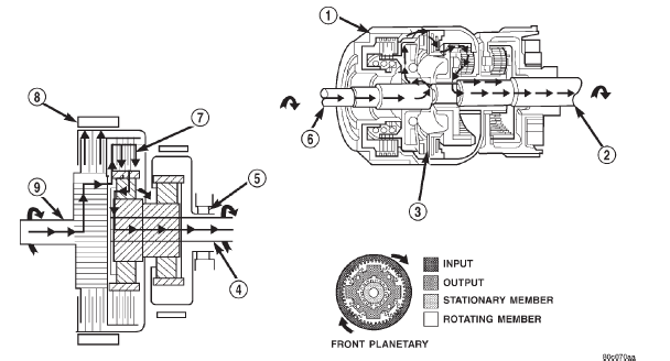
Fig. 7 Second Gear Powerflow
1 - KICKDOWN BAND APPLIED
2 - OUTPUT SHAFT
3 - REAR CLUTCH ENGAGED
4 - OUTPUT SHAFT
5 - OVER-RUNNING CLUTCH FREE-WHEELING
6 - INPUT SHAFT
7 - REAR CLUTCH APPLIED
8 - KICKDOWN BAND APPLIED
9 - INPUT SHAFT
DIRECT DRIVE POWERFLOW
The vehicle has accelerated and reached the shift point for the 2-3 upshift into direct drive (Fig. 8).
When the shift takes place, the front band is released, and the front clutch is applied. The rear clutch stays applied as it has been in all the forward gears. With the front clutch now applied, engine torque is now on the front clutch retainer, which is locked to the sun gear driving shell. This means that the sun gear is now turning in engine rotation (clockwise) and at engine speed. The rear clutch is still applied so engine torque is also still on the front annulus gear. If two members of the same planetary set are driven, direct drive results. Therefore, when two members are rotating at the same speed and in the same direction, it is the same as being locked up.
The rear planetary set is also locked up, given the sun gear is still the input, and the rear annulus gear must turn with the output shaft. Both gears are turning in the same direction and at the same speed.
The front and rear planet pinions do not turn at all in direct drive. The only rotation is the input from the engine to the connected parts, which are acting as one common unit, to the output shaft.
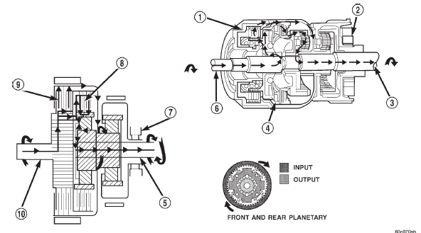
Fig. 8 Direct Drive Powerflow
1 - FRONT CLUTCH APPLIED
2 - OVER-RUNNING CLUTCH FREE-WHEELING
3 - OUTPUT SHAFT
4 - REAR CLUTCH APPLIED
5 - OUTPUT SHAFT
6 - INPUT SHAFT
7 - OVER-RUNNING CLUTCH FREE-WHEELING
8 - REAR CLUTCH APPLIED
9 - FRONT CLUTCH APPLIED
10 - INPUT SHAFT
 Fluid. Torque converter. Oil pump
Other materials:
Automatic Temperature Control (ATC). Operating Tips
Automatic Temperature Control (ATC)
Automatic Operation
1. Push the AUTO button on the faceplate or press the
"AUTO" button on the touchscreen.
2. Adjust the temperature you would like the system to
maintain by adjusting the driver and passenger temperature
buttons on the faceplate or buttons ...

