Jeep Cherokee (XJ): Alignment
WHEEL ALIGNMENT DESCRIPTION Wheel alignment involves the correct positioning of
the wheels in relation to the vehicle. The positioning
is accomplished through suspension and steering
linkage adjustments. An alignment is considered
essential for efficient steering, good directional stability
and to minimize tire wear. The most important
measurements of an alignment are caster, camber
and toe position (Fig. 1).
CAUTION: Never attempt to modify suspension or
steering components by heating or bending.
CAUTION: Components attached with a nut and
cotter pin must be torqued to specification. Then if
the slot in the nut does not line up with the cotter
pin hole, tighten nut until it is aligned. Never loosen
the nut to align the cotter pin hole.
NOTE: Periodic lubrication of the front suspension/
steering system components may be required. Rubber
bushings must never be lubricated. Refer to
Group 0, Lubrication And Maintenance for the recommended
maintenance schedule. OPERATION
1 - WHEEL CENTERLINE SUSPENSION AND STEERING SYSTEM CONDITION POSSIBLE CAUSES CORRECTION PRE-ALIGNMENT Before starting wheel alignment, the following
inspection and necessary corrections must be completed.
Refer to Suspension and Steering System
Diagnosis Chart for additional information. WHEEL ALIGNMENT Before each alignment reading, the vehicle should
be jounced (rear first, then front). Grasp each
bumper at the center and jounce the vehicle up and
down several times. Always release the bumper in
the down position. Set the front end alignment to
specifications with the vehicle at its NORMAL RIDE
HEIGHT. CAMBER The wheel camber angle is preset. This angle is not
adjustable and cannot be altered. CASTER Before checking the caster of the front axle for correct
angle, be sure the axle is not bent or twisted.
Road test the vehicle, make left and right turns. If
the steering wheel returns to the center position
unassisted, the caster angle is correct. If steering
wheel does not return toward the center position
unassisted, an incorrect caster angle is probable.
Caster can be adjusted by installing the appropriate
size shims (Fig. 2). NOTE: Changing caster angle will also change the
front propeller shaft angle. The propeller shaft
angle has priority over caster. Refer to Group 3 Differential
& Driveline for additional information.
1 - SHIM TOE POSITION (LHD) NOTE: The wheel toe position adjustment is the
final adjustment. The engine must remain running
during the entire toe position adjustment. NOTE: Once the toe setting is correct, the steering
wheel can be re-centered by adjusting only the drag
link. TOE POSITION (RHD) NOTE: The wheel toe position adjustment is the
final adjustment. The engine must remain running
during the entire toe position adjustment.
1 - PITMAN ARM
1 - PITMAN ARM NOTE: Make sure the toe setting does not change
during clamp tightening. NOTE: Make sure the toe setting does not change
during clamp tightening. NOTE: Once the toe setting is correct, the steering
wheel can be re-centered by adjusting only the drag
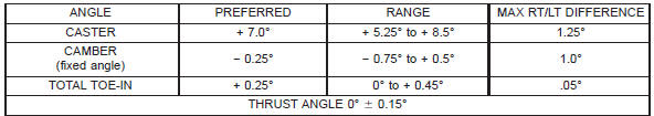
link. ALIGNMENT NOTE: All alignment specifications are in degrees.
Description and operation
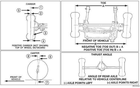
Fig. 1 Wheel Alignment Measurements
2 - NEGATIVE CAMBER ANGLE
3 - PIVOT CENTERLINE
4 - SCRUB RADIUS
5 - TRUE VERTICAL
6 - KING PIN
7 - VERTICAL
8 - POSITIVE CASTERDiagnosis and testing
FRONT END NOISE
EXCESSIVE PLAY IN
STEERING
FRONT WHEELS SHIMMY
VEHICLE INSTABILITY
EXCESSIVE STEERING
EFFORT
VEHICLE PULLS TO ONE
SIDE DURING BRAKING
VEHICLE LEADS OR
DRIFTS FROM STRAIGHT
AHEAD DIRECTION ON
UNCROWNED ROAD
KNOCKING, RATTLING
OR SQUEAKING
IMPROPER TRACKING
Service procedures
Fig. 2 Caster Adjustment
2 - SUSPENSION ARM
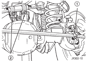
Fig. 4 Drag Link and Tie Rod Clamp (LHD)
Fig. 3 Steering Linkage (LHD)
2 - ADJUSTMENT SLEEVE
3 - DRAG LINK
4 - TIE ROD
5 - STEERING DAMPENER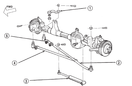
Fig. 5 Steering Linkage (RHD)
2 - DRAG LINK
3 - STEERING DAMPNER
4 - TIE ROD
5 - ADJUSTMENT SLEEVE
Specifications


Other materials:
Door sill scuff plate. Assist handle. B-pillar trim
Door sill scuff plate
REMOVAL
(1) Remove the screws attaching the door sill scuff
plate to the door sill (Fig. 67).
(2) Separate the scuff plate from the door sill.
Fig. 67 Door Sill Scuff Plate
1 - REAR DOOR SILL SCUFF PLATE
2 - FRONT DOOR SILL SCUFF PLATE
INSTALLATION
(1) Position th ...