Jeep Cherokee (XJ): Description and operation
DESCRIPTION Two different ignition systems are used. One type
is used for the 2.5L 4-cylinder engine. The other is
used for the 4.0L 6-cylinder engine. OPERATION 2.5L 4-Cylinder Engine: The ignition system is controlled by the Powertrain
Control Module (PCM).
The ignition system consists of: 4.0L 6-Cylinder Engine: The 4.0L 6-cylinder engine uses a one-piece coil
rail containing three independent coils. Although cylinder
firing order is the same as 4.0L engines of previous
years, spark plug firing is not. The 3 coils dualfire
the spark plugs on cylinders 1-6, 2-5 and/or 3-4.
When one cylinder is being fired (on compression
stroke), the spark to the opposite cylinder is being
wasted (on exhaust stroke). The one-piece coil bolts
directly to the cylinder head. Rubber boots seal the
secondary terminal ends of the coils to the top of all
6 spark plugs. One electrical connector (located at
the rear end of the coil rail) is used for all three coils.
Because of coil design, spark plug cables (secondary
cables) are not used on either engine. A distributor
is not used with the 4.0L engine.
The ignition system is controlled by the Powertrain
Control Module (PCM).
The ignition system consists of: DESCRIPTION The 2.5L engine is equipped with a camshaft
driven mechanical distributor (Fig. 1) containing a
shaft driven distributor rotor. The distributor is also
equipped with an internal camshaft position (fuel
sync) sensor (Fig. 1).
1 - SYNC SIGNAL GENERATOR OPERATION The distributor does not have built in centrifugal
or vacuum assisted advance. Base ignition timing
and all timing advance is controlled by the Powertrain
Control Module (PCM). Because ignition timing
is controlled by the PCM, base ignition timing is
not adjustable.
The distributor is locked in place by a fork with a
slot located on the distributor housing base. The distributor
holddown clamp bolt passes through this slot
when installed. Because the distributor position is
locked when installed, its rotational position can not
be changed. Do not attempt to modify the distributor
housing to get distributor rotation.
Distributor position will have no effect on ignition
timing. The position of the distributor will
determine fuel synchronization only.
All distributors contain an internal oil seal that
prevents oil from entering the distributor housing.
The seal is not serviceable. DESCRIPTION Resistor type spark plugs are used.
Spark plug resistance values range from 6,000 to
20,000 ohms (when checked with at least a 1000 volt
spark plug tester). Do not use an ohmmeter to
check the resistance values of the spark plugs.
Inaccurate readings will result. OPERATION To prevent possible pre-ignition and/or mechanical
engine damage, the correct type/heat range/number
spark plug must be used.
Always use the recommended torque when tightening
spark plugs. Incorrect torque can distort the
spark plug and change plug gap. It can also pull the
plug threads and do possible damage to both the
spark plug and the cylinder head.
Remove the spark plugs and examine them for
burned electrodes and fouled, cracked or broken porcelain
insulators. Keep plugs arranged in the order
in which they were removed from the engine. A single
plug displaying an abnormal condition indicates
that a problem exists in the corresponding cylinder.
Replace spark plugs at the intervals recommended in
Group O, Lubrication and Maintenance
Spark plugs that have low mileage may be cleaned
and reused if not otherwise defective, carbon or oil
fouled. Also refer to Spark Plug Conditions.
CAUTION: Never use a motorized wire wheel brush
to clean the spark plugs. Metallic deposits will
remain on the spark plug insulator and will cause
plug misfire. DESCRIPTION Spark plug cables are used only on the 2.5L
engine. They are sometimes referred to as secondary
ignition wires. OPERATION The spark plug cables transfer electrical current
from the ignition coil(s) and/or distributor, to individual
spark plugs at each cylinder. The resistive spark
plug cables are of nonmetallic construction. The
cables provide suppression of radio frequency emissions
from the ignition system. DESCRIPTION A single ignition coil is used with the 2.5L 4-cylinder
engine. The coil is not oil filled. The coil windings
are embedded in an epoxy compound. This provides
heat and vibration resistance that allows the coil to
be mounted on the engine. OPERATION The Powertrain Control Module (PCM) opens and
closes the ignition coil ground circuit for ignition coil
operation.
Battery voltage is supplied to the ignition coil positive
terminal from the ASD relay. If the PCM does
not see a signal from the crankshaft and camshaft
sensors (indicating the ignition key is ON but the
engine is not running), it will shut down the ASD circuit.
Base ignition timing is not adjustable. By controlling
the coil ground circuit, the PCM is able to set
the base timing and adjust the ignition timing
advance. This is done to meet changing engine operating
conditions. DESCRIPTION A one-piece coil rail assembly containing three
individual coils is used on the 4.0L 6-cylinder engine
(Fig. 2). The coil rail must be replaced as one assembly.
The bottom of the coil is equipped with 6 individual
rubber boots (Fig. 2) to seal the 6 spark plugs to
the coil. Inside each rubber boot is a spring. The
spring is used for a mechanical contact between the
coil and the top of the spark plug. These rubber boots
and springs are a permanent part of the coil and are
not serviced separately.
(1) The coil is bolted directly to the cylinder head
(Fig. 3). One electrical connector (located at rear of
coil) is used for all three coils. OPERATION Although cylinder firing order is the same as 4.0L
Jeep engines of previous years, spark plug firing is
not. The 3 coils dual-fire the spark plugs on cylinders
1-6, 2-5 and/or 3-4. When one cylinder is being fired
(on compression stroke), the spark to the opposite
cylinder is being wasted (on exhaust stroke).
Battery voltage is supplied to the three ignition
coils from the ASD relay. The Powertrain Control
Module (PCM) opens and closes the ignition coil
ground circuit for ignition coil operation.
Base ignition timing is not adjustable. By controlling
the coil ground circuit, the PCM is able to set
the base timing and adjust the ignition timing advance. This is done to meet
changing engine operating
conditions.
1 - CYL. #6
1 - COIL RAIL The ignition coil is not oil filled. The windings are
embedded in an epoxy compound. This provides heat
and vibration resistance that allows the ignition coil
to be mounted on the engine.
Because of coil design, spark plug cables (secondary
cables) are not used. The cables are integral
within the coil rail. DESCRIPTION The Crankshaft Position (CKP) sensor is located
near the outer edge of the flywheel (starter ringear). OPERATION Engine speed and crankshaft position are provided
through the CKP sensor. The sensor generates pulses
that are the input sent to the Powertrain Control
Module (PCM). The PCM interprets the sensor input
to determine the crankshaft position. The PCM then
uses this position, along with other inputs, to determine
injector sequence and ignition timing.
The sensor is a hall effect device combined with an
internal magnet. It is also sensitive to steel within a
certain distance from it.
The flywheel/drive plate has groups of four notches
at its outer edge. On 2.5L 4-cylinder engines there
are two sets of notches (Fig. 4). On 4.0L 6-cylinder
engines there are three sets of notches (Fig. 5).
The notches cause a pulse to be generated when
they pass under the sensor. The pulses are the input
to the PCM. For each engine revolution there are two
groups of four pulses generated on 2.5L 4-cylinder
engines. There are 3 groups of four pulses generated
on 4.0L 6-cylinder engines.
The trailing edge of the fourth notch, which causes
the pulse, is four degrees before top dead center
(TDC) of the corresponding piston.
The engine will not operate if the PCM does not
receive a CKP sensor input. DESCRIPTION On the 2.5L 4-cylinder engine the Camshaft Position
(CMP) sensor is located in the distributor. OPERATION The sensor contains a hall effect device called a
sync signal generator to generate a fuel sync signal.
This sync signal generator detects a rotating pulse
ring (shutter) on the distributor shaft. The pulse ring
rotates 180 degrees through the sync signal generator.
Its signal is used in conjunction with the Crankshaft
Position (CKP) sensor to differentiate between
fuel injection and spark events. It is also used to synchronize
the fuel injectors with their respective cylinders.
1 - CRANKSHAFT POSITION SENSOR
1 - CRANKSHAFT POSITION SENSOR When the leading edge of the pulse ring (shutter)
enters the sync signal generator, the following occurs:
The interruption of magnetic field causes the voltage
to switch high resulting in a sync signal of approximately
5 volts.
When the trailing edge of the pulse ring (shutter)
leaves the sync signal generator, the following occurs:
The change of the magnetic field causes the sync signal
voltage to switch low to 0 volts. DESCRIPTION The Camshaft Position Sensor (CMP) on the 4.0L
6-cylinder engine is bolted to the top of the oil pump
drive shaft assembly (Fig. 6). The sensor and drive
shaft assembly is located on the right side of the
engine near the oil filter (Fig. 7).
1 - CAMSHAFT POSITION SENSOR OPERATION The CMP sensor contains a hall effect device called
a sync signal generator to generate a fuel sync signal.
This sync signal generator detects a rotating
pulse ring (shutter) on the oil pump drive shaft (Fig.
6). The pulse ring rotates 180 degrees through the
sync signal generator. Its signal is used in conjunction
with the crankshaft position sensor to differentiate
between fuel injection and spark events. It is also
used to synchronize the fuel injectors with their
respective cylinders.
1 - OIL FILTER When the leading edge of the pulse ring (shutter)
enters the sync signal generator, the following occurs:
The interruption of magnetic field causes the voltage
to switch high resulting in a sync signal of approximately
5 volts.
When the trailing edge of the pulse ring (shutter)
leaves the sync signal generator, the following occurs:
The change of the magnetic field causes the sync signal
voltage to switch low to 0 volts. DESCRIPTION The electrical ignition switch is located on the
steering column. It is used as the main on/off switching
device for most electrical components. The
mechanical key lock cylinder is used to engage/disengage
the electrical ignition switch. OPERATION Vehicles equipped with an automatic transmission
and a floor mounted shifter: a cable is
used to connect the interlock device in the steering
column assembly, to the transmission floor shift
lever. This interlock device is used to lock the transmission
shifter in the PARK position when the key
lock cylinder is rotated to the LOCKED or ACCESSORY
position. The interlock device within the steering
column is not serviceable. If repair is necessary,
the steering column assembly must be replaced.
Refer to Group 19, Steering for procedures.
If the ignition key is difficult to rotate to or from
the LOCK or ACCESSORY position, it may not be
the fault of the key cylinder or the steering column
components. The brake transmission shift interlock
cable may be out of adjustment. Refer to Brake
Transmission Shift Interlock Cable Adjustment in
Group 21, Transmissions for adjustment procedures.
Vehicles equipped with an automatic transmission
and a steering column mounted shifter:
an interlock device is located within the steering column.
This interlock device is used to lock the transmission
shifter in the PARK position when the key
lock cylinder is in the LOCKED or ACCESSORY
position. If it is difficult to rotate the key to or from
the LOCK or ACCESSORY position, the interlock
device within the steering column may be defective.
This device is not serviceable. If repair is necessary,
the steering column assembly must be replaced.
Refer to Group 19, Steering for procedures.
Vehicles equipped with a manual transmission
and a floor mounted shifter: on certain models,
a lever is located on the steering column behind
the ignition key lock cylinder. The lever must be
manually operated to allow rotation of the ignition
key lock cylinder to the LOCK or ACCESSORY position.
If it is difficult to rotate the key to the LOCK or
ACCESSORY position, the lever mechanism may be
defective. This mechanism is not serviceable. If
repair is necessary, the steering column assembly
must be replaced. Refer to Group 19, Steering for
procedures.
On other models, the ignition key cylinder must be
depressed to allow it to be rotated into the LOCK or
ACCESSORY position. If it is difficult to rotate the
key to the LOCK or ACCESSORY position, the lock
mechanism within the steering column may be defective.
This mechanism is not serviceable. If repair is
necessary, the steering column assembly must be
replaced. Refer to Group 19, Steering for procedures.Ignition system
Distributor-2.5L engine
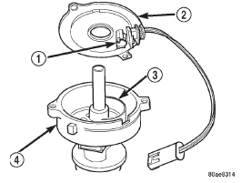
Fig. 1 Distributor and Camshaft Position Sensor- 2.5L Engine
2 - CAMSHAFT POSITION SENSOR
3 - PULSE RING
4 - DISTRIBUTOR ASSEMBLYSpark plugs
Spark plug cables-2.5L engine
Ignition coil-2.5L engine
Ignition coil-4.0L engine
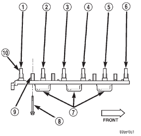
Fig. 2 Ignition Coil Assembly-4.0L 6-Cylinder Engine
2 - CYL. #5
3 - CYL. #4
4 - CYL. #3
5 - CYL. #2
6 - CYL. #1
7 - COILS (3)
8 - MOUNTING BOLTS (4)
9 - BOLT BASES (4)
10 - RUBBER BOOTS (6)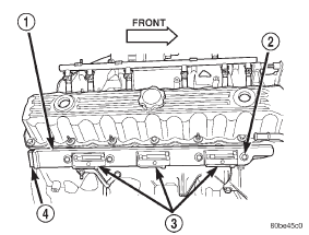
Fig. 3 Coil Location-4.0L Engine
2 - COIL MOUNTING BOLTS (4)
3 - COIL
4 - COIL ELECTRICAL CONNECTIONCrankshaft position sensor
Camshaft position sensor-2.5L engine
Fig. 4 Sensor Operation-2.5L 4-Cyl. Engine
2 - NOTCHES
3 - FLYWHEEL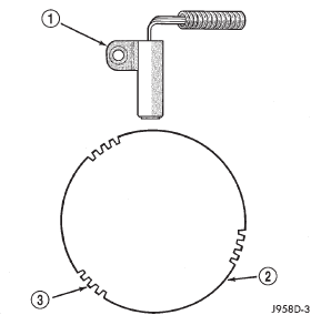
Fig. 5 Sensor Operation-4.0L 6-Cyl. Engine
2 - FLYWHEEL
3 - FLYWHEEL NOTCHESCamshaft position sensor-4.0L
engine
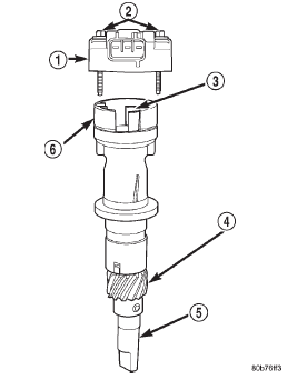
Fig. 6 CMP and Oil Pump Drive Shaft-4.0L Engine
2 - MOUNTING BOLTS (2)
3 - PULSE RING
4 - DRIVE GEAR (TO CAMSHAFT)
5 - OIL PUMP DRIVESHAFT
6 - SENSOR BASE (OIL PUMP DRIVESHAFT ASSEMBLY)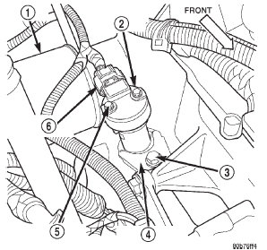
Fig. 7 CMP Location-4.0L Engine
2 - CAMSHAFT POSITION SENSOR
3 - CLAMP BOLT
4 - HOLD-DOWN CLAMP
5 - MOUNTING BOLTS (2)
6 - ELEC. CONNECTORIgnition switch and key lock
cylinder


Other materials:
Sentry key
The Sentry Key Immobilizer system prevents unauthorized
vehicle operation by disabling the engine. The
system does not need to be armed or activated. Operation
is automatic, regardless of whether the vehicle is locked
or unlocked.
The system uses a Key Fob with a factory-mated Remote
Keyless ...