Jeep Cherokee (XJ): Description and operation
DESCRIPTION An electrically operated engine starting system is
standard factory-installed equipment on this model.
The starting system is designed to provide the vehicle
operator with a convenient, efficient and reliable
means of cranking and starting the internal combustion
engine used to power the vehicle and all of its
accessory systems. The starting system includes the
following major components: The starting system consists of two separate circuits.
A high-amperage feed circuit that feeds the
starter motor between 150 and 350 amperes of battery
current, and a low-amperage control circuit that
operates on less than 20 amperes of battery current.
The starting system high-amperage feed circuit
includes the battery, the battery cables, the contact
disc portion of the starter solenoid, and the starter
motor. The following starting system feed circuit
components are covered in more detail in other areas
of this service manual: The starting system low-amperage control circuit
includes the ignition switch, the clutch pedal position
switch (manual transmission), the park/neutral position
switch (automatic transmission), the starter
relay, the electromagnetic windings of the starter
solenoid, and the wire harnesses that connect these
components. The following starting system control
circuit components are covered in more detail in
other areas of this service manual: Following are general descriptions of the starter
relay and the starter motor. See the owner's manual
in the vehicle glove box for more information on the
features, use and operation of the starting system.
Refer to Starting System in the index of this service
manual for the location of complete wiring diagrams
for the starting system.
NOTE: This group covers both Left-Hand Drive
(LHD) and Right-Hand Drive (RHD) versions of this
model. Whenever required and feasible, the RHD
versions of affected vehicle components have been
constructed as mirror-image of the LHD versions.
While most of the illustrations used in this group
represent only the LHD version, the diagnostic and
service procedures outlined can generally be
applied to either version. Exceptions to this rule
have been clearly identified as LHD or RHD, if a
special illustration or procedure is required. OPERATION If the vehicle is equipped with a manual transmission,
the clutch pedal position switch is installed in
series between the ignition switch and the coil battery
terminal of the starter relay. This normally open
switch prevents the starter relay from being energized
when the ignition switch is turned to the
momentary Start position, unless the clutch pedal is
fully depressed. This feature prevents starter motor
operation while the clutch disc and the flywheel are
engaged. The starter relay coil ground terminal is
always grounded on vehicles with a manual transmission.
If the vehicle is equipped with an automatic transmission,
battery voltage is supplied through the lowamperage
control circuit to the coil battery terminal
of the starter relay when the ignition switch is
turned to the momentary Start position. The park/
neutral position switch is installed in series between
the starter relay coil ground terminal and ground.
This normally open switch prevents the starter relay
from being energized and the starter motor from
operating unless the automatic transmission gear
selector is in the Neutral or Park positions.
When the starter relay coil windings are energized,
the relay directs battery current to the starter solenoid
coil windings. When the starter solenoid coil
windings are energized, the solenoid directs battery
current to the starter motor, which cranks the engine
by engaging the starter pinion gear with the starter
ring gear. Once the engine starts, the ignition switch
key is released by the vehicle operator. When the
ignition switch key is released, the switch automatically
returns to the On position, which de-energizes
the starting system. DESCRIPTION
1 - STARTER SOLENOID The starter motors used for both the 2.5L and the
4.0L engines available in this model are not interchangeable
(Fig. 1). However, each of these starter
motors incorporates several of the same features to
create a reliable, efficient, compact, lightweight and
powerful unit. Both starters feature high torque
direct current electric motors. Inside both starter
motors the commutator of the rotating motor armature
is contacted by four brushes. The starter motor
for the 2.5L engine is driven by four permanent magnet
field poles, while the starter motor for the 4.0L
engine is driven by four electromagnetic field coils
wound around four pole shoes. The 2.5L starter
motor is rated at 1.2 kilowatts (about 1.6 horsepower)
output at 12 volts, while the 4.0L starter
motor is rated at 1.4 kilowatts (about 1.9 horsepower)
output at 12 volts.
These starter motors are equipped with a planetary
gear reduction (intermediate transmission) system.
The planetary gear reduction system consists of
a gear that is integral to the output end of the electric
motor armature shaft that is in continual
engagement with a larger gear that fits on a spline
on the input end of the starter pinion gear shaft.
This feature makes it possible to reduce the dimensions
of the starter. At the same time, it allows
higher armature rotational speed and delivers
increased torque through the starter pinion gear. Both starter motors use an overrunning clutch and
starter pinion gear unit to engage and drive the
starter ring gear, which is integral to the flywheel
(manual transmission) or torque converter drive
plate (automatic transmission) mounted on the rear
crankshaft flange. Shims are available and can be
used to adjust the 2.5L starter motor mounting position
to correct for improper starter pinion gear to
starter ring gear engagement.
The starter motors for both engines are activated
by an integral heavy duty starter solenoid switch
mounted to the overrunning clutch housing. This
electromechanical switch connects and disconnects
the feed of battery current to the starter motor
through a movable contact on one end of the solenoid
core or plunger. At the same time, the solenoid
plunger actuates a shift fork that engages and disengages
the starter pinion gear with a starter ring
gear. The starter solenoid has two electromagnetic
windings or coils, a pull-in coil and a hold-in coil. The
pull-in coil requires more battery current and produces
a stronger electromagnetic field than the
hold-in coil.
Both starter motors are serviced only as a unit
with their starter solenoids, and cannot be repaired.
If either component is faulty or damaged, the entire
starter motor and starter solenoid unit must be
replaced. OPERATION When the starter solenoid pull-in coil windings are
energized the solenoid plunger is drawn into the electromagnetic
coil. The solenoid plunger pulls the shift
lever in the starter motor. This engages the starter
overrunning clutch and pinion gear with the starter
ring gear on the manual transmission flywheel or on
the automatic transmission torque converter drive
plate. As the solenoid plunger reaches the end of its
travel, it moves the solenoid contact disc to complete
the high-amperage starter feed circuit and energizes
the solenoid hold-in coil windings. Battery current
now flows between the solenoid battery terminal and
the starter field terminal, energizing the starter and
cranking the engine.
Once the engine starts, the overrunning clutch protects
the starter motor from damage by allowing the
starter pinion gear to spin faster than the pinion
shaft. When the solenoid plunger hold-in coil is deenergized,
the solenoid plunger return spring returns
the plunger to its relaxed position. This causes the
solenoid contact disc to open the starter feed circuit,
and the shift lever to disengage the overrunning
clutch and pinion gear unit from the starter ring
gear. DESCRIPTION
The starter relay (Fig. 2) is an electromechanical
device that switches battery current to the pull-in
coil of the starter solenoid when the ignition switch
is turned to the Start position. The starter relay is
located in the Power Distribution Center (PDC), in
the engine compartment. See the fuse and relay layout
label affixed to the inside surface of the PDC
cover for starter relay identification and location.
The starter relay is a International Standards
Organization (ISO) relay. Relays conforming to the
ISO specifications have common physical dimensions,
current capacities, terminal patterns, and terminal
functions.
The starter relay cannot be repaired or adjusted
and, if faulty or damaged, it must be replaced. OPERATION The ISO relay consists of an electromagnetic coil, a
resistor or diode, and three (two fixed and one movable)
electrical contacts. The movable (common feed) relay
contact is held against one of the fixed contacts (normally
closed) by spring pressure. When the electromagnetic
coil is energized, it draws the movable contact
away from the normally closed fixed contact, and holds
it against the other (normally open) fixed contact.
When the electromagnetic coil is de-energized,
spring pressure returns the movable contact to the
normally closed position. The resistor or diode is connected
in parallel with the electromagnetic coil in the
relay, and helps to dissipate voltage spikes that are
produced when the coil is de-energized.Starting system
Starter motor
Fig. 1 Starter MotorsStarter relay
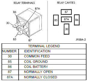
Fig. 2 Starter Relay


Other materials:
Passenger side airbag door. Airbag control module. Clockspring
Passenger side airbag door
WARNING:
THE AIRBAG SYSTEM IS A SENSITIVE, COMPLEX
ELECTROMECHANICAL UNIT. BEFORE
ATTEMPTING TO DIAGNOSE OR SERVICE ANY AIRBAG
SYSTEM OR RELATED STEERING WHEEL,
STEERING COLUMN, OR INSTRUMENT PANEL
COMPONENTS YOU MUST FIRST DISCONNECT
AND ISOLATE THE ...