Jeep Cherokee (XJ): Refrigerant. Refrigerant lines. Refrigerant line couplers
DESCRIPTION The refrigerant used in this air conditioning system
is a HydroFluoroCarbon (HFC), type R-134a.
Unlike R-12, which is a ChloroFluoroCarbon (CFC),
R-134a refrigerant does not contain ozone-depleting
chlorine. R-134a refrigerant is a non-toxic, non-flammable,
clear, and colorless liquefied gas.
Even though R-134a does not contain chlorine, it
must be reclaimed and recycled just like CFC-type
refrigerants. This is because R-134a is a greenhouse
gas and can contribute to global warming. OPERATION R-134a refrigerant is not compatible with R-12
refrigerant in an air conditioning system. Even a
small amount of R-12 added to an R-134a refrigerant
system will cause compressor failure, refrigerant oil
sludge or poor air conditioning system performance.
In addition, the PolyAlkylene Glycol (PAG) synthetic
refrigerant oils used in an R-134a refrigerant system
are not compatible with the mineral-based refrigerant
oils used in an R-12 refrigerant system.
R-134a refrigerant system service ports, service
tool couplers and refrigerant dispensing bottles have
all been designed with unique fittings to ensure that
an R-134a system is not accidentally contaminated
with the wrong refrigerant (R-12). There are also
labels posted in the engine compartment of the vehicle
and on the compressor identifying to service technicians
that the air conditioning system is equipped
with R-134a. DESCRIPTION The refrigerant lines and hoses are used to carry
the refrigerant between the various air conditioning system components. A
barrier hose design with a
nylon tube, which is sandwiched between rubber layers,
is used for the R-134a air conditioning system on
this vehicle. This nylon tube helps to further contain
the R-134a refrigerant, which has a smaller molecular
structure than R-12 refrigerant. The ends of the
refrigerant hoses are made from lightweight aluminum
or steel, and commonly use braze-less fittings.
Any kinks or sharp bends in the refrigerant plumbing
will reduce the capacity of the entire air conditioning
system. Kinks and sharp bends reduce the
flow of refrigerant in the system. A good rule for the
flexible hose refrigerant lines is to keep the radius of
all bends at least ten times the diameter of the hose.
In addition, the flexible hose refrigerant lines should
be routed so they are at least 80 millimeters (3
inches) from the exhaust manifold. OPERATION High pressures are produced in the refrigerant system
when the air conditioning compressor is operating.
Extreme care must be exercised to make sure
that each of the refrigerant system connections is
pressure-tight and leak free. It is a good practice to
inspect all flexible hose refrigerant lines at least once
a year to make sure they are in good condition and
properly routed.
The refrigerant lines and hoses are coupled with
other components of the HVAC system with peanutblock
style fittings. A stat-O seal type flat steel gasket
with a captured compressible O-ring, is used to
mate plumbing lines with A/C components to ensure
the integrity of the refrigerant system.
The refrigerant lines and hoses cannot be repaired
and, if faulty or damaged, they must be replaced. DESCRIPTION Spring-lock type refrigerant line couplers are used
to connect many of the refrigerant lines and other
components to the refrigerant system. These couplers
require a special tool for disengaging the two coupler
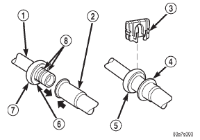
halves. OPERATION The spring-lock coupler is held together by a garter
spring inside a circular cage on the male half of the
fitting (Fig. 5). When the two coupler halves are connected,
the flared end of the female fitting slips
behind the garter spring inside the cage on the male
fitting. The garter spring and cage prevent the flared
end of the female fitting from pulling out of the cage.
Two O-rings on the male half of the fitting are
used to seal the connection. These O-rings are compatible
with R-134a refrigerant and must be replaced
with O-rings made of the same material.
Secondary clips are installed over the two connected
coupler halves at the factory for added blowoff
protection. In addition, some models have a plastic
ring that is used at the factory as a visual indicator
to confirm that these couplers are connected. After
the coupler is connected, the plastic indicator ring is
no longer needed; however, it will remain on the
refrigerant line near the coupler cage.
1 - MALE HALF SPRING-LOCK COUPLERRefrigerant
Refrigerant lines
Refrigerant line couplers

Fig. 5 Spring-Lock Coupler - Typical
2 - FEMALE HALF SPRING-LOCK COUPLER
3 - SECONDARY CLIP
4 - CONNECTION INDICATOR RING
5 - COUPLER CAGE
6 - GARTER SPRING
7 - COUPLER CAGE
8 - "O" RINGS
 High pressure cut-off switch. High pressure relief valve. Low pressure cycling clutch switch
 Refrigerant oil. Refrigerant system service port. Vacuum check valve
Other materials:
Brake/Transmission Shift Interlock System. Nine-Speed Automatic Transmission. Gear Ranges
Brake/Transmission Shift Interlock System
This vehicle is equipped with a Brake Transmission Shift
Interlock system (BTSI) that holds the shift lever in PARK
unless the brakes are applied. To shift the transmission
out of PARK, the ignition must be turned to the ON/
RUN position (engine running ...
